background image

nVent.com  |  3

2. Calculate the total heating cable length required

Length = A + B + C + D + E + F + G + H

A  Pipe length x spiraling ratio
B  4 ft x # gate/globe valves x valve length (ft) x spiraling ratio
C  2 ft x # ball/butterfly valves x valve length (ft) x spiraling ratio
D  2 ft x # flanges x pipe diameter (ft) x spiraling ratio
E  2 ft x # pipe supports v pipe diameter (ft) x spiraling ratio
F  1 ft for each power connection
G  2 ft for each splice connection
H  3 ft for each tee connection

=  Total heating cable length (ft)

3. Determine the maximum heating cable circuit length allowed.

See Table 3 on the next page. Ensure that your circuits do not 

exceed the maximum circuit length listed in Table 3. If necessary, 

use additional shorter circuits.

Example (taken from Example 2 [on metal pipe], page 3):

Pipe length: 

50 ft

Spiral ratio: 

1.3 (from Table 1, page 3)

Globe valves: 

3 (each 0.5 ft long)

Pipe supports: 

10 supports for 1 in pipe

Power connections: 

1

Splice connections: 

1

WinterGard heating cable required:
A
  Pipe length x spiral ratio  =  50  ft x 1.3 

= 65.0 ft

B  3 globe valves (0.5 ft each) =  4  ft x 3 x 0.5 x 1.3 

=  7.8 ft

C  0 ball/butterfly valves 

=  0   

=  0

D  0 flanges 

=  0   

=  0

E  10 pipe supports 

=  2  ft x 10 x 0.085* x 1.3  =  2.2 ft

F  1 power connection 

=  1  ft x 1  

=  1.0 ft

G  1 splice connection 

=  2  ft x 1 

=  2.0 ft

H  0 tee connection 

=  0   

=  0

Total heating cable length required 

=  78.0 ft

*1 in pipe diameter / 12 in per foot = 0.085 foot

HEATING CABLE INSTALLATION

1. Prepare for installation

•  Store the heating cable in a clean, dry place.
•  Complete piping pressure test.
•  Review the WinterGard heating cable design and compare to 

materials received to verify that the proper WinterGard heating 

cable and accessories are available. The WinterGard heating 

cable will have the heating cable type printed on the outer 

jacket.

•  Walk the system and plan the routing of the WinterGard heating 

cable on the pipe.

2. Cut the heating cable to length

•  Cut the heating cable to the length required. This can be 

done before or after the cable is attached to the pipe. Leave a 

minimum of 1 foot extra heating cable for connection to power. 

For splice and tee connections, leave a minimum of 1 foot for 

each section of heating cable. WinterGard heating cable can be 

cut to length without affecting its heat output per foot.

•  Protect the heating cable ends from moisture or mechanical 

damage if they will be left exposed before connection.

3. Position and attach heating cable to pipe

•  Be sure all piping to be traced is dry.
•  Install heating cable, using straight tracing, spiraling, or multiple 

tracing according to the “Heating cable selection and design” 

section on page 2.

•  For straight tracing, install the heating cable on a lower half of 

the pipe; for example, in the 4 o’clock or 8 o’clock position.

•  Be sure to install the additional heating cable required for 

valves, flanges, etc. as indicated in Step 2 of the “Heating cable 

selection and design” section.

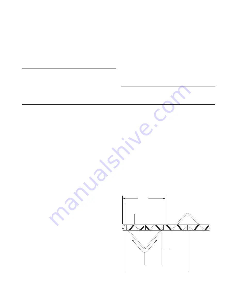
•  When the design calls for spiraling, begin by suspending a 

loop every 10 feet as shown in Figure 1. To determine the loop 

length, obtain the spiral factor from Table 1 or 2 and multiply 

by 10. For example, if a spiral factor of 1.3 is called for, leave a 

13-foot loop of heating cable at every 10-foot section of pipe. 

Grasp the loop in its center and wrap it around the pipe. Even 

out the distance between spirals by sliding the wraps along the 

pipe. Use glass tape to secure the center of the loop to the pipe. 

Secure the heating cable flat to the pipe to obtain good contact.

•  Tape WinterGard heating cable to the pipe at 2-foot intervals 

using RAYCHEM H903 fiberglass application tape or nylon  

cable ties. Do not use vinyl electrical tape, duct tape, metal 

bands, or wire.

4. Install heating cable end seals, splices, tees, and power 

connection

•  Test each circuit before installing the H908 ground-fault device, 

according to the instructions in the “Heating cable testing and 

maintenance” section.

•  Install all end seals, splices, tees, and power connection prior to 

plugging in.

•  Follow the H908 kit installation instructions beginning on page 8.
•  Use only weatherproof receptacles approved for wet locations 

when installing WinterGard Wet H612 heating cable with the 

H908 Power Connection Kit for Roof and Gutter De-Icing 

Applications.

5. Check the installation

•  Prior to installing thermal insulation, make sure the heating 

cable is free of mechanical damage (from cuts, clamps, etc.) 

and thermal damage (from solder, overheating, etc.).

•  Visually check all power connections, end seals, splices, and tees.
•  Using a megohmmeter, test each circuit according to the 

instructions in the “Heating cable testing and maintenance” 

section (page 4) both before and after installing the  

thermal insulation.

Figure 1. Spiraled heat tracing

10 feet

Glass tape

(typical)

Heating

cable

Tape after

spiraling 

heating

cable on 

pipe

Wrap loops

in opposite

direction

Pull heating

cable loop

length

Apply glass

tape before

spiraling

heating cable

on pipe

Summary of Contents for RAYCHEM H908

Page 1: ...he black heating cable core is conductive and can short It must be properly insulated and kept dry Keep components and heating cable ends dry before and during installation Damaged bus wires can overheat or short Do not break braid or bus wire strands when scoring the jacket or core Bus wires will short if they contact each other Keep bus wires separated Heat damaged components can short Use a hea...

Page 2: ...1 o clock or 1 o clock position and at the 4 o clock and 8 o clock positions Example 1 Pipe size 1 in Lowest air temp 0 F Insulation thickness 1 2 in Metal pipe WinterGard H311 Plastic pipe WinterGard Plus H611 H621 WinterGard Wet H612 H622 Example 2 Pipe size 2 1 2 in Lowest air temp 20 F Insulation thickness 1 2 in Metal pipe 1 3 WinterGard Plus H611 or WinterGard Wet H612 Use 1 3 feet of heatin...

Page 3: ...before connection 3 Position and attach heating cable to pipe Be sure all piping to be traced is dry Install heating cable using straight tracing spiraling or multiple tracing according to the Heating cable selection and design section on page 2 For straight tracing install the heating cable on a lower half of the pipe for example in the 4 o clock or 8 o clock position Be sure to install the addit...

Page 4: ...ms inspect heating cables for signs of damage and verify the components are correctly installed If physical damage is found the entire damaged section must be removed and a new section of heating cable spliced in using only approved H910 splice kits If physical damage cannot be found the complete circuit should be removed and replaced with new heating cable To verify the ground fault circuit is fu...

Page 5: ... gutter and downspout The cable running in the gutter should remain against the bottom of the gutter Extend the top of each heating cable loop beyond where the wall joins the roof nVent recommends 2 foot clip spacing along the roof edge See the Heating cable design section Table 5 for spacing and layout information Use WinterGard H913 H914 roof clips to attach heating cable to the roof surface One...

Page 6: ...If physical damage is found the entire damaged section must be removed and a new section of heating cable spliced in using only approved H910 splice kits If physical damage cannot be found the complete circuit should be removed and replaced with new heating cable To verify the ground fault circuit is functioning test the H908 before each use Push in the test button The indicator light must turn of...

Page 7: ...atherproofed outlet approved for wet locations H913 H914 Roof clip H910 Tee End seal Clamp ties two places Clamp ties two places Power connection splice included with the H908 H908 Ground fault equipment protection device Weatherproofed outlet approved for wet locations Drip loops Drip loop Drip loop Note In all locations route and secure cable to avoid possible mechanical damage such as from ladd...

Page 8: ...nd wire Plug in cord 3 in Note Instructions generally show heating cable with braid and outer jacket Cables with no outer jacket look slightly different from those illustrated H908 POWER CONNECTION KIT Identify heating cable Stripped end of ground fault protection device 5 in tube 8 in tube 2 3 4 in 1 2A For all heating cables For H311 and H611 heating cables only Slide 8 inch tube and 5 inch tube...

Page 9: ...cket Score between bus wires at inner jacket Bend core to break free at inner jacket Peel core and any remaining material from bus wires Notch core at the end Twist back and peel bus wires from core Slide 1 8 inch x 1 inch shrink tubes over bus wires To shrink tubing move heat source continuously from side to side While shrinking ensure that tubes remain up against black core Trim bus wires For H6...

Page 10: ...e black wire Finish bus wire preparation Apply 5 inch shrink tube Connect bus wires Apply mastic to bus wires Trim bus wires Squeeze the mastic together Center the 5 inch heat shrinkable tube over the splice Make sure tube extends over the end of each heating cable and the cord Shrink the tube completely Start at the middle and work toward each end Keep heating after tube has shrunk to melt mastic...

Page 11: ...ect braid to ground wire Wrap black cloth tape evenly around crimp and splice Cover crimp completely Center the 8 inch heat shrinkable tube over the splice Make sure that the tube extends over the end of the heating cable and cord Shrink the tube completely Start at the middle and work toward each end Keep heating after tube has shrunk to melt adhesive inside tube Total heating time should be abou...

Page 12: ... braid Firmly push end seal onto the cable at least 11 2 inches Some gel may ooze out Do not twist or try to remove the end seal during or after insertion Do not reuse an end seal Firmly push end seal onto the cable at least 11 2 inches Some gel may ooze out Do not twist or try to remove the end seal during or after insertion Do not reuse an end seal Cleanly cut off the end of the cable Push the b...

Page 13: ...pproved for wet locations Make sure that Cord label is readily visible Indicator light on the ground fault equipment protection device is on Receptacle is properly weatherproofed Ground fault equipment protection device and power connection splice will not be submerged For pipe freeze protection For pipe freeze protection For roof and gutter de icing For roof and gutter de icing Plug the heating c...

Page 14: ...ect incidental or consequential Notwithstanding the foregoing nVent shall have no liability whatsoever unless a Buyer promptly notifies nVent in writing after discovery of an alleged nonconformity and includes a detailed explanation of the alleged nonconformity b Buyer promptly returns the goods to nVent postage prepaid at the address obtained by calling Customer Service at 1 800 545 6258 or 650 2...

Reviews: