background image

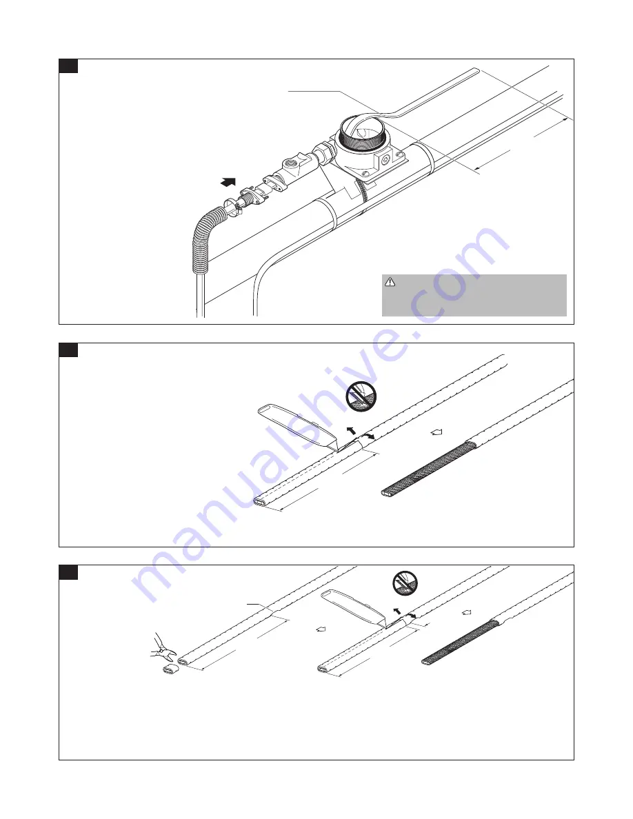
 WARNING: Correct grommet must be 

used for heating cable being installed or 

electrical hazard could result.

•  Select correct grommet from table on 

page 2.

•  Slide parts onto heating cable as shown.
•  Slide heating cable through fittings 

and box.

•  Repeat steps 2 through 5 for each 

additional heating cable.

16 in. 

(41 cm)

min.

Important

For VPL-CT only:

Locate indentation

(bus wire connection)

at this point

5

14 1/2 in.

(37 cm)

Do Not

Cut Braid

6A

•  Lightly score outer jacket as shown.
•  Bend heating cable to break jacket at 

score, then peel off jacket.

Go to step 7.

For BTV-CT, HBTV-CT, QTVR-CT, HQTV-CT, FHP, XTV-CT, HXTV-CT, and LBTV2-CT heating cables

14 1/2 in.

(37 cm)

1/2 in.

(13 mm)

Do Not

Cut Braid

Indentation

(bus wire connection)

15 in.

(38 cm)

6B

•  Cut heating cable 15 in. (38 cm) from the indentation (bus wire connection).
•  Lightly score outer jacket as shown.
•  Bend heating cable to break jacket at score, then peel off jacket.

Go to step 7.

For VPL-CT heating cables

nVent.com  

|

  4

Summary of Contents for Raychem HAK-C-100

Page 1: ...Connection Kit for Division 1 Hazardous Locations Installation Instructions HAK C 100 ...

Page 2: ...Keep the flame moving to avoid overheating blistering or charring the heat shrinkable tubes Avoid heating other components Replace any damaged parts Health Hazard Prolonged or repeated contact with the sealant in the core sealer may cause eye or skin irritation Wash hands thoroughly Overheating or burning the sealant will produce fumes that may cause polymer fume fever Avoid contamination of cigar...

Page 3: ... CT R 10HXTV1 CT R 10HXTV2 CT R Heating Cable for FM Only Grommet 15HXTV1 CT R 15HXTV2 CT R 20HXTV1 CT R 20HXTV2 CT R FHP 2 E FHP 3 C 5BTV1 CT B 5BTV2 CT B 8BTV 1 CT E 8BTV 2 CT E 10BTV1 CT E 10BTV2 CT E 10QTVR1 CT C C 10QTVR2 CT C C Heating Cable for FM Only Grommet 20QTVR1 CT E 20QTVR2 CT E All XTV1 CT T3 R All XTV2 CT T3 R All XTV1 CT T2 R All XTV2 CT T2 R All VPL1 CT R All VPL2 CT R LBTV2 CT K...

Page 4: ...ction at this point 5 14 1 2 in 37 cm Do Not Cut Braid 6A Lightly score outer jacket as shown Bend heating cable to break jacket at score then peel off jacket Go to step 7 For BTV CT HBTV CT QTVR CT HQTV CT FHP XTV CT HXTV CT and LBTV2 CT heating cables 14 1 2 in 37 cm 1 2 in 13 mm Do Not Cut Braid Indentation bus wire connection 15 in 38 cm 6B Cut heating cable 15 in 38 cm from the indentation bu...

Page 5: ...er jacket Bend and snap core Peel core from bus wire Remove any remaining core material For LBTV2 CT go to Step A on page 11 For all other heating cables go to step 10 Lightly score inner jacket around and down as shown Bend heating cable to break jacket at score then peel off jacket 7 6 1 2 in 165 mm 8 For VPL CT only Push braid back to create a pucker At pucker use a screwdriver to open braid Be...

Page 6: ...15 mm as shown For VPL CT go to Step 11 For all other heating cables go to Step 12 1 1 2 in 38 mm 11 Cut off and discard end of core sealer legs For VPL CY only Tubes 12 13 For VPL CT heating cables Refer to material safety data sheet RAY5510 If needed retwist and straighten bus wires Insert bus wires into guide tubes as shown Make sure all strands go into tubes Push core sealer onto the heating c...

Page 7: ... insulation resistance values in the Heating Cable Test 1 section of the FM Required Division 1 Installation Record on page 14 Test B Connect the test leads as shown Measure the insulation resistance between the braid and the metal pipe IMPORTANT Be sure to isolate the braid from the ground before performing Test B To perform Test B after sealing compound is poured into sealing fitting as braid ma...

Page 8: ...tion Resistance Criteria A clean dry properly installed circuit should measure thousands of megohms regardless of heating cable length or measuring voltage 0 to 2500 Vdc The following criteria are provided to assist in determining acceptability of an installation where optimum conditionsmay not apply All insulation resistance values should be greater than or equal to 1000 megohms Insulation resist...

Page 9: ...2500 Vdc Insulation resistance criteria is defined in Step 16b page 7 If the readings vary with the voltage refer to the Troubleshooting Guide page 12 Test A Connect the test leads as shown Measure the insulation resistance between the heating cable bus wires and the braid Record the Test A insulation resistance values in the Post Thermal Insulation Heating Cable Test 2 section of the FM Required ...

Page 10: ...fter pouring into fitting Refer to material safety data sheet VEN0024 Weather seal the bracket and flexible tube entries Mix sealing compound according to manufacturer s recommendation on container Sealing mixture should be a pourable paste Pour into sealing fitting Install plugs Packing fiber 22 Refer to material safety data sheet VEN0025 Pack fiber around heating cable as shown Be careful not to...

Page 11: ...ce End Seal Heating cable Heating cable Braid Braid Heating cable Heating cable Heating cable Braid Braid Heating cable Braid 26 Make connections to terminal block terminal block is installed floating in the junction box Inspect each core seal for proper placement Stow wires in box Install cover and gasket Tighten cover set screw 25 For power connections only Install conduit and sealing fitting wi...

Page 12: ...y pinch between bus wires and hold for 5 seconds to create a seal Go to step 15 and continue with installation Use the heat shrinkable core sealer with LBTV2 CT in place of the cold applied core sealer shown in Step 12 on page 5 WARNING Fire Hazard Heat guns or minitorches can cause fire or explosion in hazardous areas Be sure there are no flammable materials or vapors in the area before using the...

Page 13: ...after the charging period Heavily wetted surfaces between energized parts Same as above Circuit breaker GFPD trips Nick or cut in heating cable or power feed wire with moisture present Replace damaged cable Circuit breaker undersized Resize the circuit breaker and wiring if applicable Circuit oversized Same as above Startup at too low a temperature Same as above Defective circuit breaker Replace c...

Page 14: ...a high resistance connection Recrimp with the correct procedure Tighten set screws on terminal block Control thermostat is wired in normally open position Rewire in the normally closed position Pipe is at an elevated temperature Reduce pipe temperature Check the pipe temperature Verify the power output of heating cable See note below for method Heating cable has been exposed to excessive moisture ...

Page 15: ... mA Tee connection Spice INSTALLATION INSTRUCTIONS Correct components per manufacturer s specification Seal fittings opened and inspected properly poured Ground leakage device tested INSULATION RESISTANCE TESTING Minimum insulation resistance must be 1000 mΩ If less than 1000 mΩ see Troubleshooting Guide pages 12 and 13 Heating Cable Test 1 refer to Step 16a and b of HAK C 100 installation instruc...

Page 16: ...Fax 86 21 2412 1688 cn thermal info nvent com Latin America Tel 1 713 868 4800 Fax 1 713 868 2333 thermal info nvent com nVent com 2018 nVent All nVent marks and logos are owned or licensed by nVent Services GmbH or its affiliates All other trademarks are the property of their respective owners nVent reserves the right to change specifications without notice Raychem IM H56573 HAKC100 EN 1805 ...

Reviews: