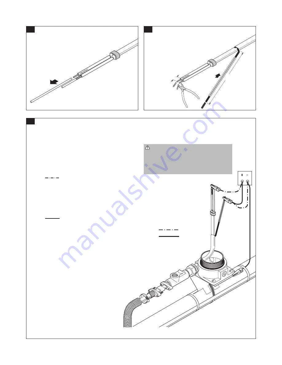
• Trim bus wires (except VPL-CT).
• Trim braid.
• Slip the green/yellow tube onto the braid.
Test A
Test B
14
16A
14 1/2 in.
(37 cm)
3/8 in.
(9 mm)
15
• Remove the tubes and dispose of them in a plastic bag.
Heating Cable Test 1
Following the test method outlined below, perform an insulation resistance test on the heating cable using a 2500 Vdc tester.
Test Method
• Perform Tests A and B at 500, 1000, and 2500 Vdc.
• Insulation resistance criteria is defined in Step 16b (page 7).
• If the readings vary with the voltage refer to the Troubleshooting
Guide (page 12).
Test A
• Connect the test leads as shown.
• Measure the insulation resistance between the heating cable bus
wires and the braid.
• Record the Test A insulation resistance values in the “Heating
Cable Test 1” section of the FM Required Division 1 Installation
Record on page 14.
Test B
• Connect the test leads as shown.
• Measure the insulation resistance between the braid and the
metal pipe.
IMPORTANT:
- Besuretoisolatethebraidfromthegroundbefore
performing Test B.
- ToperformTestBaftersealingcompoundispouredinto
sealing fitting (as braid may contact sealing fitting or
junction box), see illustration in Post-Thermal-Insulation
Heating Cable Test 2, Step 21, page 8.
• RecordtheTestBinsulationresistancevaluesinthe
“Heating Cable Test 1” section of the FM Required
Division 1 Installation Record on page 14.
WARNING: Fire Hazard. Megohmmeter
test can produce sparks. Be sure there are
no flammable vapors in the area before
performing this test. Follow all site safety
guidelines when working in hazardous areas.
nVent.com
|
7


