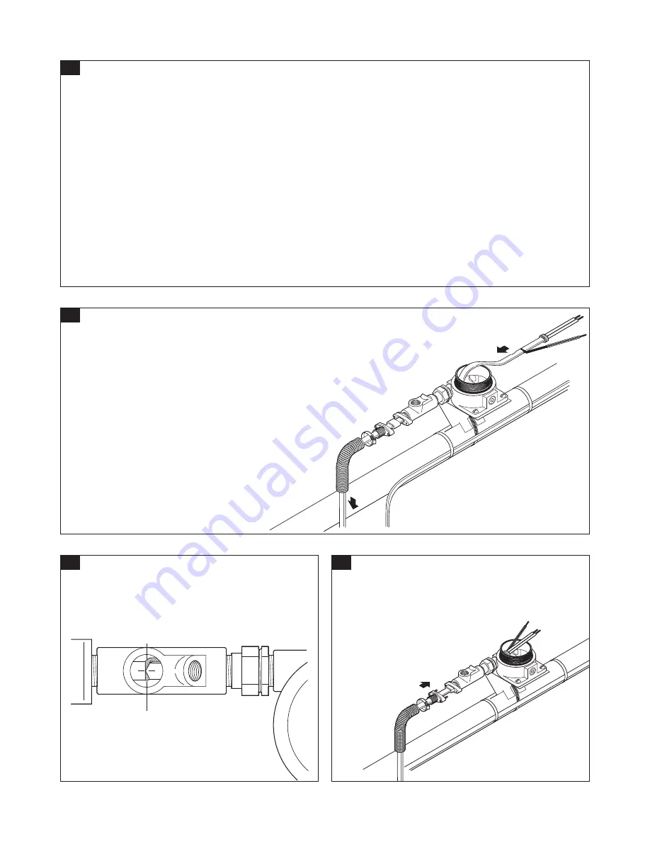
Center
18
19
• Be sure green/yellow tubing does not
extend into sealing fitting.
• Center heating cable as shown.
• Position grommet in gland cavity.
• Tighten compression gland screws, being
careful not to change position of heating cable
in sealing fitting
(see Step 18).
• Install flex tubing onto compression
gland.
• Tighten tubing clamp.
17
• Carefully pull heating cable back through box,
making sure core sealer remains positioned at
5/8 in. (15 mm) mark. Continue pulling until end of
outer jacket is centered in sealing fitting opening
(see Step 18).
16B
Insulation Resistance Criteria
A clean, dry, properly installed circuit should measure thousands of megohms, regardless of heating cable length
or measuring voltage(0 to 2500 Vdc). The following criteria are provided to assist in determining acceptability of an
installation where optimum conditionsmay not apply:
• All insulation resistance values should be greater than or equal to 1000 megohms.
• Insulation resistance values from Test A, for any particular circuit, should not vary more than 25% as a function of
measuring voltage.
• Insulation resistance values from Test B, for any particular circuit, should not vary more than 25% as a function of
measuring voltage.
If any of the above conditions is not met, consult the Troubleshooting Guide (page 12).
nVent.com
|
8


