14579-030 (PXIe System)
R1.5, April 2021
8 Slot PXIe Backplane (23007-508)
9
3.4 System Synchronisation Clocks
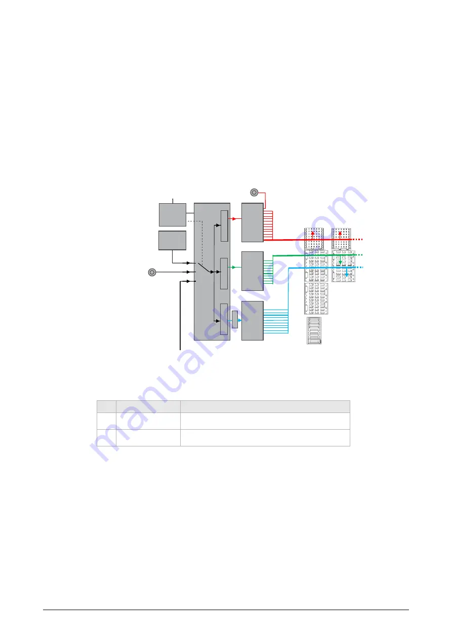
Acc. to the PXI specifications, the Schroff PXIe system routes the PXI_CLK10 to slot 1-8 and
PXIe_CLK100 and PXIe_SYNC100 to the peripheral slots 2-8.
PXI_CLK10 is also routed to the external BNC connector 10 MHz REF OUT at the chassis rear
side.
All clocks/timing signals are generated by the PXI-5 compliant Schroff PXIe Clock Module.
When a 10 MHz reference clock signal is present at the System Timing Slot or the rear panel
connector 10 MHz REF IN, PXI_CLK10, PXIe_CLK100 and PXIe_SYNC100 are phase-locked to
this reference clock signal according to the following table:
The source for the reference signal is selected automatically.
Mode
Ext. 10 MHz REF In
Backplane Clock Module
1
10 MHz clock present
10 MHz REF IN, PXI_CLK10, PXIe_CLK100 and PXIe_SYNC100 are
aphase-locked to reference clock signal from
Ext. 10 MHz REF In
2
-
10 MHz REF IN, PXI_CLK10, PXIe_CLK100 and PXIe_SYNC100 are
generated by the Clock Module
P
X
I_CLK
1
0
P
X
Ie
_CL
K10
0
P
X
Ie
_S
YN
C1
0
0
XO
10 MHz
10 MHz
REF IN
PLL
Buffer
Buffer
Buffer
Auto-mode:
1 -> 2
2
I2C-Control
10 MHz
REF OUT
Slot 1
Slot 2
Schroff PXIe Clock Module
3
1
T
-> 3
Summary of Contents for Schroff 14579-030
Page 1: ...8 Slot PXIe System User s Manual Product Number 14579 030 Doc No 63972 388_R1 5 April 2021...
Page 4: ...14579 030 PXIe System II R1 5 April 2021...
Page 29: ...14579 030 PXIe System R1 5 April 2021 3Dimensions 25...
Page 30: ...14579 030 PXIe System 26 3Dimensions R1 5 April 2021...
Page 31: ......


