14579-030 (PXIe System)
R1.5, April 2021
Cooling
17
4.1 Temperature Settings
1 NTC temperature sensor is located in top of the card cage and one behind. They are
connected to the CMM. The highest temperature level is the reference for the fan speed.
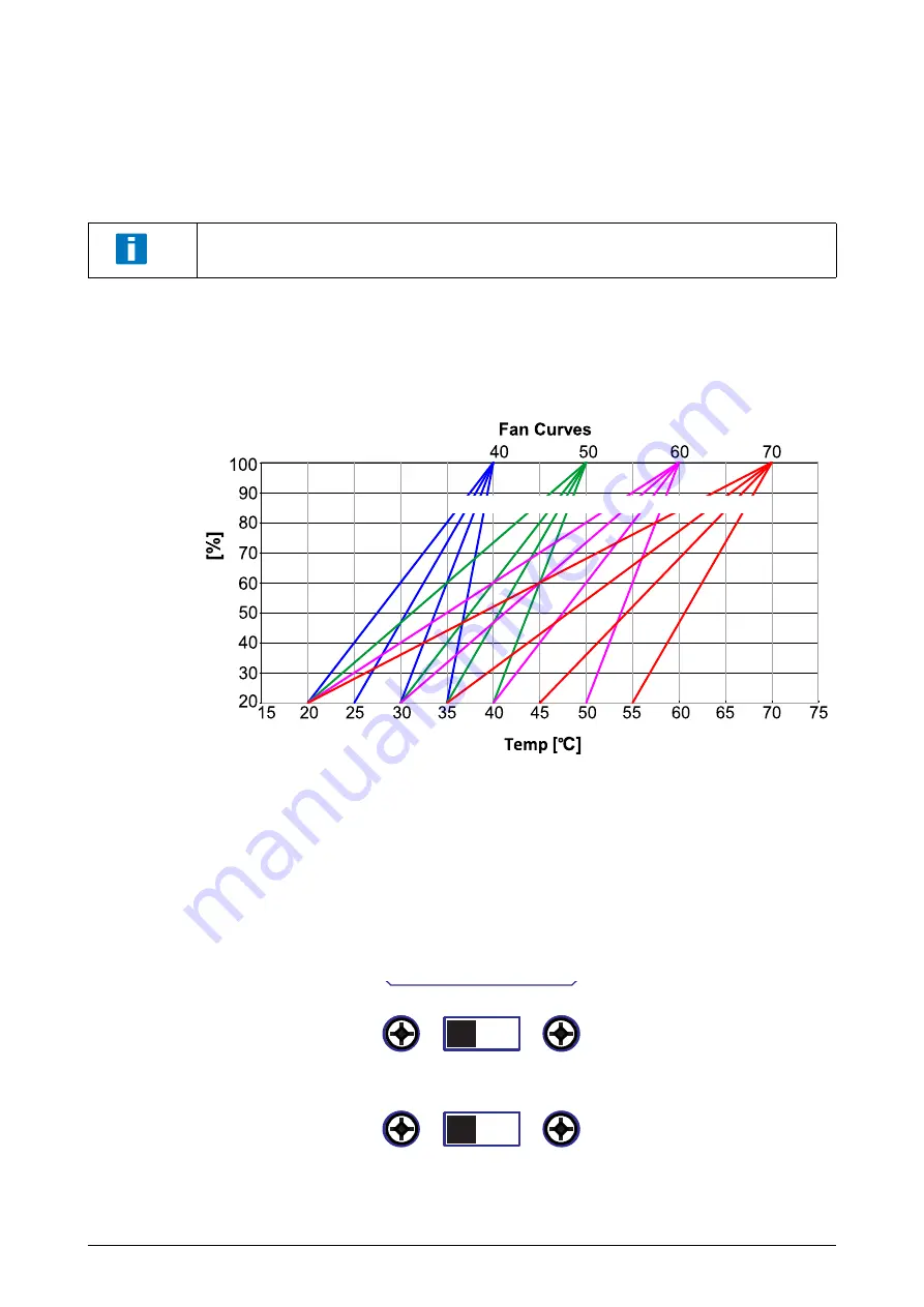
The fan speed is controlled by the CMM depending on a fan curve stored in a CMM register.
16 fan curves are available and can be selected by the SCHROFF embedded controller, the
default fan curve is “5“.
A manual fan speed control where the embedded controller sets the fan speed in % is also
possible. For more information see the CMM user manual, 63972-391.
4.1.1 Maximum cooling
For maximum cooling performance, set the fan speed switch at the chassis rear side to
“
MAX“
. The fans will rotate permanently at 100%.
To ensure proper fan control, place the PXIe Module with the highest heat dissipation in
the slots directly underneath the NTC temperature sensor.
123
Fan Speed
5 6 7
9 10 11
0
4
8
12 13 14 15
INHIBIT MODE
DEF
MAN
FAN SPEED
AUTO
MAX
Summary of Contents for Schroff 14579-030
Page 1: ...8 Slot PXIe System User s Manual Product Number 14579 030 Doc No 63972 388_R1 5 April 2021...
Page 4: ...14579 030 PXIe System II R1 5 April 2021...
Page 29: ...14579 030 PXIe System R1 5 April 2021 3Dimensions 25...
Page 30: ...14579 030 PXIe System 26 3Dimensions R1 5 April 2021...
Page 31: ......


