background image

CPCI System Subrack 1 U

Service

24579-078

www.schroff.biz

11

R1.0, January 14, 2008

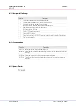
4.3  Scope of Delivery

4.4  Accessories

4.5  Spare Parts

On request.

Quantity

Description

1

19” subrack, shielded, black powder coated (RAL9005)

1

CPCI backplane (PICMG2.0 R.3.0), 2 slot 6 U, system slot left 

1

Front card cage for max. 2 boards 6 U 160 mm deep
IEEE guide rails inc. ESD clips (ESD clip assembled at the right)

1

Rear card cage for max. 2 boards 6 U 80 mm deep
IEEE guide rails inc. ESD clips

1

Slot fo a CPCI plug-in power supply

1

Complete AC/DC cabling

1

Power input module with IEC 320-C14 connector, mains/line switch, mains/line filter and fuses

1

Fan Tray, hot swappable

Order No.

Description

13100-141

250 W plug-in power supply with wide range input

20848-7xx

Slot covers with front panel and EMC shielding for vacant slots. For dimensions, please see 
catalogue.

34562-8xx

Slot covers for vacant slots. For dimensions, please see catalogue.

24579-03x

Printed Circuit Board covers (perforated solder side covers). For dimensions, please see  
catalogue

Summary of Contents for SCHROFF 24579-078

Page 1: ...CPCI System Subrack 1 U User s Manual Product No 24579 078 January 14 2008 Doc No 63972 165_R1 0...

Page 2: ...anagement System to EN ISO 9001 2000 The company cannot accept any liability for errors or misprints The company reserves the right to amendments of technical specifications due to further development...
Page 3: ...ystem Overview 3 2 3 Subrack 4 2 4 CPCI Backplane 4 2 5 Power Supply 5 2 5 1 Grounding Earthing 5 2 5 2 CPCI Plug In AC Power Supply Order separately 6 2 6 Cooling 7 3 Installation 8 3 1 General Insta...

Page 4: ...CPCI System Subrack 1 U 24579 078 www schroff biz II R1 0 January 14 2008...

Page 5: ...e is no valid approval for this unit In order to enable stand alone functionality additional elements are required An operational system is achieved only by way of appropiate CPCI boards The completio...

Page 6: ...e safety precautions to avoid accidents before starting to work with parts that carry dangerous voltages Caution This is the user caution symbol It indicates a condition where damage of the equipment...

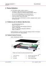
Page 7: ...wer input module with IEC 320 C14 connector mains line switch mains line filter and fuses 2 1 References and Architecture Specifications User Manual CPCI Backplanes Order no 73972 101 Technical Data S...

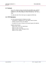
Page 8: ...Boards 6 U 4 HP 80 mm deep The right guide rails of the board cage are equipped with ESD clips 2 4 CPCI Backplane The horizontally assembled 6 U Backplane provides CompactPCI bus PICMG2 0 R 3 0 with S...

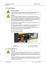
Page 9: ...protective earth conductor of the power cable Hazardous voltage Parts of the power supply may be exposed with hazardous voltage Always remove mains line connector before carry out any assembly work C...

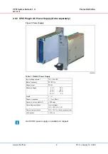
Page 10: ...e 10006814 Input voltage nominal 100 240 VAC Mains Frequency 50 60 Hz Output max 250 W Output voltages 3 3 5 0 12 0 12 0 V V V V 40 40 5 5 2 A A A A Ripple 1 Dynamic response 1 or 60 mV Recovery time...

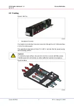
Page 11: ...through four 12 VDC axial fans 13 5 m h 8 cfm each The operating temperature is from 0 C to 50 C but note that the power supply starts derating at 50 C Figure 5 Airflow 12308800 1 Backplane Connector...

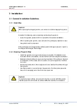
Page 12: ...pen rack whenever possible If installation in an enclosed rack is unavoidable ensure that the rack has adequate ventilation Maintain ambient airflow to ensure normal operation If the airflow is blocke...

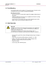
Page 13: ...t system at the bottom avoid uneven mechanical loading of the rack 3 3 Initial Operation Ensure that the system has not been damaged during transport storage or assembly Check the Protective Earth PE...

Page 14: ...MC regulations and therefore a CE marking is not required However when CPCI cards are assembled according to specification the systems fulfill the requirements in accordance with EMC Directive 2004 10...

Page 15: ...max 2 boards 6 U 80 mm deep IEEE guide rails inc ESD clips 1 Slot fo a CPCI plug in power supply 1 Complete AC DC cabling 1 Power input module with IEC 320 C14 connector mains line switch mains line...

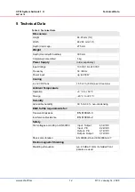
Page 16: ...ut up to 250 W Cooling 4 x 12 VDC fans 13 5 m h 8 cfm each free blow Ambient Temperature Operation 0 C to 50 C Storage 40 C to 85 C Humidity Admissible humidity 30 to 80 non condensing EMC fulfils req...

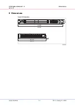
Page 17: ...CPCI System Subrack 1 U Dimensions 24579 078 www schroff biz 13 R1 0 January 14 2008 6 Dimensions Figure 6 Dimensions 10006858 465 20 482 80 42 0 283 25 304 70 13 95...

Page 18: ...CPCI System Subrack 1 U Dimensions 24579 078 www schroff biz 14 R1 0 January 14 2008...

Page 19: ......

Page 20: ...SCHROFF GMBH www schroff biz Langenalberstr 96 100 Tel 49 0 7082 794 0 Fax 49 0 7082 794 200 D 75334 Straubenhardt...

Reviews: