9
•
•
Step
Procedure
See
2
Pay attention to the air flow consideration within
the system and rack
3
Make sure that none of the package contents is
missing or damaged
4
Mount the system into a rack enclosure
5
Power on the system
6
Perform system bring-up
System Bring-Up of Managed Systems
7
[Optional] FRU replacements
Safety Warnings
Prior to the installation, please review the
. Note that some warnings may not apply
to all models.
Air Flow
NVIDIA systems are offered with two air flow patterns:
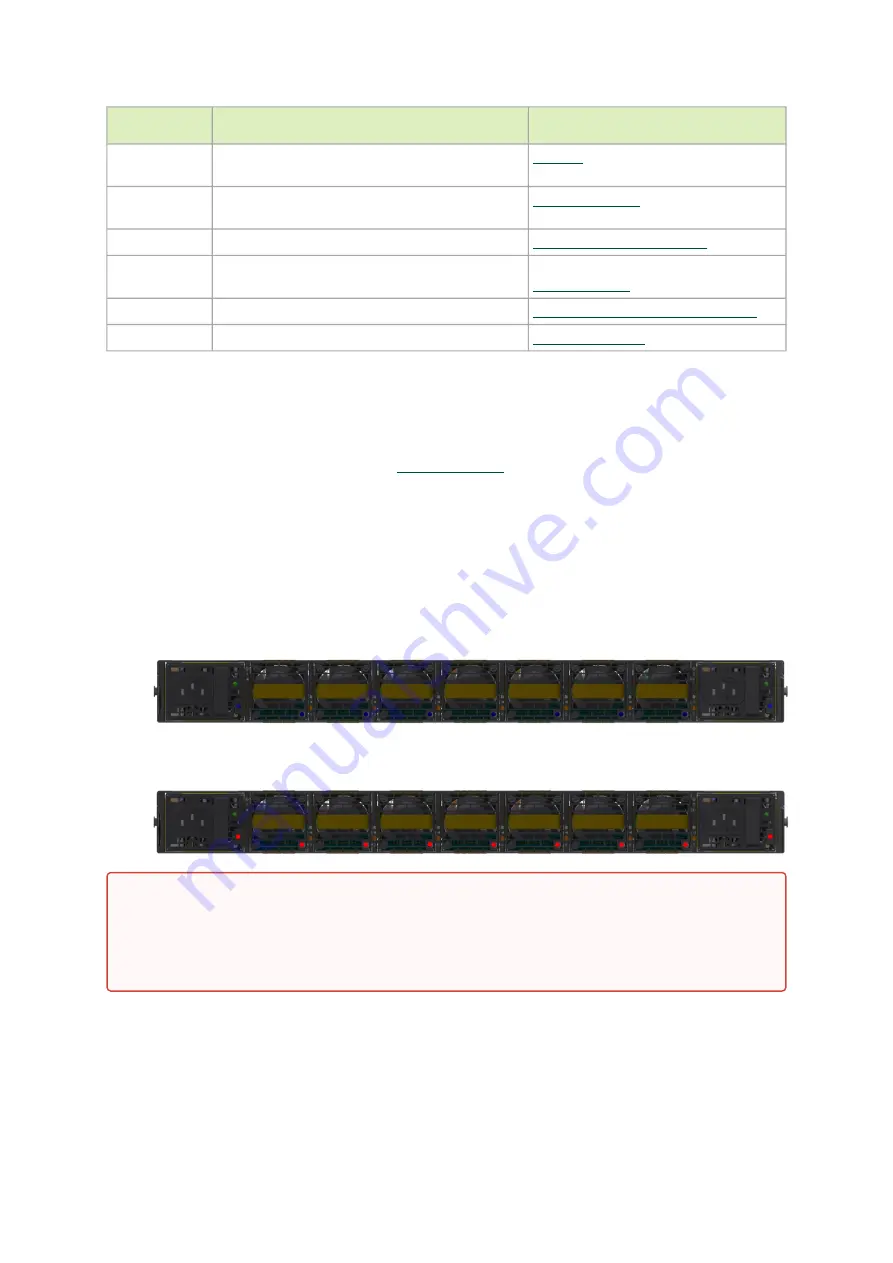
Power (rear) side inlet to connector side outlet - marked with blue dots that are placed on
the power inlet side.
Air Flow Direction Marking - Power Side Inlet to Connector Side Outlet
Connector (front) side inlet to power side outlet - marked with red dots that are placed on
the power inlet side.
Air Flow Direction Marking - Connector Side Inlet to Power Side Outlet
The table below provides an air flow color legend and respective OPN designation.
•
•
All servers and systems in the same rack should be planned with the same airflow
direction.
All FRU components need to have the same air flow direction. A mismatch in the air
flow will affect the heat dissipation.


