Nvis 5586A
Nvis Technologies Pvt. Ltd.
38
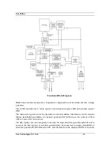
The clock generator circuit is an Intel‘s 8284 clock generator/driver. The circuit accepts a
crystal input which operates at a fundamental frequency of 6.144 MHz. (6.14 MHz was
selected since this frequency is a multiple of the baud rate clock and also provides a suitable
frequency for the CPU). The clock generator/driver divides the crystal frequency by three to
produce the 2MHz CLK signal required by the CPU. Additionally, the clock generator
performs a further divide-by-two output called PCLK (peripheral clock) which is the primary
clock signal used by the remainder of the circuits.
The clock generator/driver provides two control signal outputs which are synchronized
(internally) to the 2 MHz CLK signal; RDY (ready) and RST (reset). RST is used to reset
the Nvis 5586A to an initialized state that occurs when the RES input goes low (when power
first is applied or when the SYSTEM RESET key is pressed). The RDY output is active
(logically high) when the RDY 1 input from the wait state generator is active. As will be
explained in the next section, the RDY 1 input is active whenever onboard memory is
addressed or when a selected number of ―wait states‖ occurs.
The system can operate at either 2 MHz or 1 MHz. This is selected by a set of jumpers JP3
on the right hand side of the 8284 clock generator as shown below:
1.
2 MHz (UPPER)
2.
CLK
3.
1 MHz (LOWER)
The Nvis 5586A is supplied in 2 MHz configuration.
Bus Controller:
The 8288 is a Bus Controller which decodes status signals output by an 8089, or a maximum
mode 8086. When these signals indicate that the processor is to run a bus cycle, the 8288
issues a bus command that identifies the bus cycle as memory read, memory write, I/O read,
I/O write, etc. It also provides a signal that strobes the address into latches. The 8288
provides the drive level needed for the bus control lines in medium to large systems.
Memory:
Nvis 5586A provides 128K Bytes of EPROM loaded with monitor and 32K bytes of CMOS
RAM. The total onboard memory can be configured as follows:
EPROM
-
128K Bytes of EPROM using two 27C512.
RAM
-
32K Bytes of RAM.
The system provides two 28 Pin sockets for the EPROM area named as EVEN-ROM & ODD-
ROM and two 28 Pin sockets for the RAM area named as EVEN-RAM & ODD-RAM.
EVEN-ROM & ODD-ROM can be defined to have EPROM 27512.
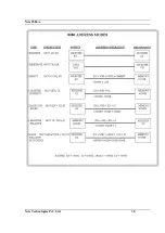
With the 20 bit address of 8086, a total of 1 Mega Bytes of memory can be addressed with
the address slot as 00000 to FFFFF. Although the total onboard memory capacity is 180K
Bytes 128K Bytes of EPROM and 32K Bytes of RAM.
8255:
8255 is a programmable peripheral interface (PPI) designed to use with 8086
Microprocessor. This basically acts as a general purpose I/O component to interface
Summary of Contents for 5586A
Page 2: ...Nvis 5586A Nvis Technologies Pvt Ltd 2...
Page 23: ...Nvis 5586A Nvis Technologies Pvt Ltd 23 Memory Read Timing in Maximum Mode...
Page 30: ...Nvis 5586A Nvis Technologies Pvt Ltd 30...
Page 48: ...Nvis 5586A Nvis Technologies Pvt Ltd 48 Diagram of module RESET power Instruction Set Note...


