


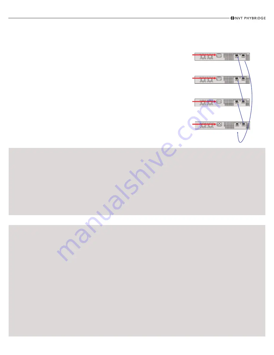
IN
OUT
IN
OUT
IN
OUT
IN
OUT
Quick Install Guide -
CLEER24-10G
Power Capabilities & Considerations
CLEER24-10G switches come standard with a hot swappable PowerWise power supply for power sharing. The switches are amongst the lowest power consuming
switches in the industry. For a redundant power configuration, daisy-chain multiple CLEER24-10G switches:
You can connect up to a maximum of 4 units for
power sharing.
• Mount all CLEER24-10G switches in the same equipment rack, with no more than 1U space between any
two units.
•
Note:
You can daisy-chain the units together while they are up and running or power them up afterward.
• Facing the rear of the units, install the DC cables (available through Phybridge) as follows:
•
Note:
To fit properly, the DC cable must be inserted into the DC input/output connector with its hairpin clip on
top.
• For the top unit, insert the first cable into the DC input connector on the left until it clicks into place. Bring
the other end of the cable down to the next unit, and connect to the DC output connector on the right.
• Continue in the same way for each pair of units, connecting the DC input (left) connector on the upper unit
to the DC output (right) connector on the lower unit.
•
Important:
For the bottom unit, the last cable from the DC input (left) connector goes up to the DC output
(right) connector on the top unit. This is required to create a fully redundant ring.
Note:
If you need to move a cable to a different DC connector on the CLEER24-10G, press the
hairpin clip
at the top of the DC cable and pull the cable out.
Warning:
All daisy-chained units must be set to the same voltage. By default, units are set to 56VDC.
Configuring the CLEER24-10G (2 Methods)
Connecting to the Admin GUI
Accessibility:
• Out of band management available through
the management port.
Default IP Address:
• MGMT = 192.168.1.1
• VLAN 1 = 192.168.100.1
Default Username & Password:
• Username: admin
• Password: admin
Steps to Change the IP Address:
1. Click on ETHERNET menu option on the top bar.
2. Once Ethernet page is displayed select IP Config.
3. Type in the new IP address and prefix into the "IP Address /
Prefix" field inside the "VLAN 1" panel.
Note:
Either an IPv4 or IPv6 address can be used. To use
DHCP, enable the "DHCP" toggle.
4. Type in the new IP address of the default gateway into the
"Default gateway:" field.
5. Click the "Apply" button next to any fields which were
modified.
6. Refer to the Administration Guide for more software details.
Connecting to CLEER24-10G:
1. Change the IP address of your PC or Laptop to
192.168.1.2
2. Connect your Ethernet port on the PC or Laptop to the
MGMT port on the CLEER24-10G.
3. Open a web browser that is up to date and browse to
http://192.168.1.1
4. Login is “admin”, password is “admin” (without quotes).
5. You are now in the Admin GUI.
Note:
Change IP addresses to avoid conflict.
(Ethernet/IP Config)
Connecting to the Command Line Interface (CLI)
Accessibility:
• Console cable connected directly to the
console port.
Console Port Serial Settings:
• 115200/8/N/1
Default Username & Password:
• Username: admin
• Password: admin
Steps to Change the IP Address:
1. The following commands must be issued to change VLAN 1's IPv4
address:
configure terminal
interface vlan 1
ip address 192.168.9.1 255.255.255.0
Substitute the provided example IP information for your own.
a) The command syntax is: ip address <ipv4_address> <subnet_mask>
2. Refer to Chapter 1 of the Administration Guide for more
information.
Connect to the Console Port:
1. Connect the RJ45 end of the serial cable to the console
port of the CLEER24-10G. Connect the serial end of
the serial cable to the serial port of your PC.
2. Configure your serial port to 115200/8/N/1.
3. Login is “admin”, password is ”admin” (without quotes).
4. You are now connected to the CLI via the console port.
Steps to Change the Management Port IP Address:
1. Log into the unit via the serial console port (115200/8/N/1).
2. The following commands must be issued to change the IP address of the
management port:
configure terminal
interface vlan 1001
ip address 192.168.10.1 255.255.255.0
Substitute the provided example IP information for your own.
a) The command syntax is: ip address <ipv4_address> <subnet_mask>
3. Refer to Chapter 1 of the Administration Guide for more information.
Steps to Save the Configuration:
1. Type in “end” or issue ctrl+z on the keyboard to return to Privileged EXEC mode.
2. The configuration is saved by issuing the “copy running-config startup-config”
command.
3. The switch configuration has now been saved.
888.901.3633 | +44 (0) 208 977 6614 | www.nvtphybridge.com
Copyright 2021 NVT Phybridge | 445-0031 REV. B | Page 2


