background image


11 

2.2 The information of the displays 


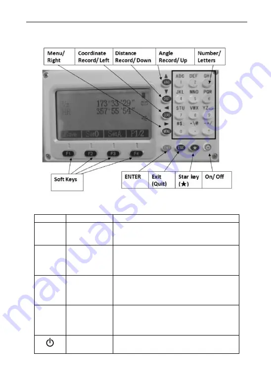
Symbols on the keyboard 

Keys   

Name   

Function   

ANG 

Angle 

measurement   

In the basic interface,enter the angle 
measurement . Under other modes, move 
the cursor up or up to select the options. 

DIST 

Distance 

measurement 

In the basic interface

enter the distance 

mode 
In the other modes

Move the Cursor down 

or down to select the options. 

CORD 

Coordinate 

measurement 

In the basic interface

enter the coordinate 

mode 
In the other modes, move the cursor left or 
page up. 

MENU 

Menu key 

Under the basic measurement 
interface,down to the menu interface. 
Under the other modes ,move the cursor 
right or page down 


Power key 

Power on/off 

Summary of Contents for NTS03

Page 1: ...OWNER S MANUAL NTS03 TOTAL STATION ...

Page 2: ...ere is no guarantee that interference will not occur in a particular installation If this equipment does cause harmful interference to radio or television reception which can be determined by turning the equipment off and on the user is encouraged to try to correct the interference by one or more of the following measures Reorient or relocate the receiving antenna Increase the separation between t...

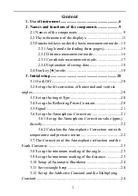
Page 3: ...rrection of horizontal and vertical angles 20 3 3 Set up the target Type 20 3 4 Set up the Reflecting Prism Constant 20 3 5 Signal 21 3 6 Set up the Atmospheric Correction 21 3 6 1 Set up the Atmospheric Correction value ppm directly 22 3 6 2 Calculate the Atmospheric Correction out with temperature and pressure sensor 22 3 7 The Correction of the Atmospheric refraction and the Earth Curvature 23 ...

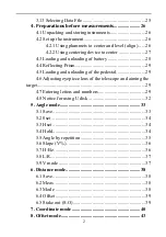
Page 4: ...4 Reflecting Prism 29 4 5 Loading and unloading of the pedestal 29 4 6 Adjusting eyepiece lens of the telescope and aiming the target 29 4 7 Entering letters and numbers 29 4 8 Notice for using U disk 32 5 Angle mode 33 5 1 Save 33 5 2 0set 34 5 3 Hset 34 5 4 Hold 34 5 5 Angle by repetition 35 5 6 Slope V 36 5 7 H Bz 36 5 8 L R 37 5 9 V mode 37 6 Distance mode 38 6 1 Save 38 6 2 Meas 38 6 3 Mode 3...

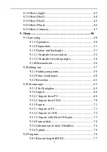
Page 5: ...setting angle 54 9 1 4Measurement 56 9 2Staking out 57 9 2 1 Staking out points 58 9 2 2 Polar coordinates 60 9 2 3 Resection 62 9 3File manager 65 9 3 1 File Dialogbox 65 9 3 2 Import 68 9 3 2 1 Import from PC 68 9 3 2 2 Import from USB 70 9 3 3 Export 71 9 3 3 1 Export to PC 71 9 3 3 2 Export to USB 72 9 3 3 3 Export with Mini USB port 73 9 3 4 Format disk 74 9 3 5 Information of disk MenInfo 74...

Page 6: ...ument constant 89 9 8 Select code file 89 9 9 Gird scale 89 9 10 Communication 90 10 Roadway 91 10 1 Inputting Roadway 91 10 1 1 Horizontal alignment 91 10 1 1 1 Element method 91 10 1 1 2 Intersection method 93 10 1 2 Vertical alignment 94 10 2 Stake out road 95 10 2 1 Selecting Roadway File 96 10 2 2 Setting station and BSS backsight point 97 10 2 3 Stake out road 97 11 Adjustments and Correctio...

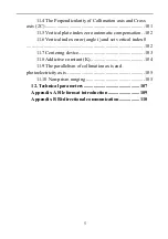
Page 7: ...11 6 Vertical index error angle i and set vertical index 0 102 11 7 Centering device 103 11 8 Addictive constant K 104 11 9 The parallelism of collimation axis and photoelectricity axis 105 11 10 Non prism ranging 105 12 Technical parameters 107 Appendix A File format introduction 109 Appendix B Bi directional communication 110 ...

Page 8: ...he series total station is equipped with absolute code dial system integrated circuit control board ranging item and microcomputer for measurements of angle and distance and for calculation display depositing and etc It can exhibit horizontal and vertical angle slope and horizontal distance and altitude difference simultaneously Furthermore it can be set to measure under different mode e g Angle m...

Page 9: ...nder no circumstances shall NWI be liable for any consequential incidental or contingent damages whatsoever Limitations and Exclusions A This warranty does not apply to instruments subject to negligence abuse accident improper operation instruments damaged in transit or damage due to unauthorized service repairs made by someone other than Northwest or other Northwest authorized service personnel C...

Page 10: ... may not be available for transportation damages These designs figures and specifications of NTS03 are subject to change without notice NWI shall not be held liable for damages resulting from errors in this instruction manual ...

Page 11: ...mes and functions of the components 2 1 Names of the components Handle Objective lens keys Display Coarse sighting device Base SD card port serial port connector Platelevel Vertical clamping and tangent screw ...

Page 12: ...10 Horizontal axis center Battery Focusing knob eyepiece Base Horizontalclamping and tangent screw Leveling screw ...

Page 13: ... Distance measurement In the basic interface enter the distance mode In the other modes Move the Cursor down or down to select the options CORD Coordinate measurement In the basic interface enter the coordinate mode In the other modes move the cursor left or page up MENU Menu key Under the basic measurement interface down to the menu interface Under the other modes move the cursor right or page do...

Page 14: ... Cursor up and down in order Turn the page under the basic measurement 0 9 Number Input number and characters and select one of menu 0 Enter the electronic bubble interface under the basic measurement Symbols Enter symbols decimals and signs Enter the interface for input height Symbols on the display Symbols Indication Vz Zenith Mode Vo The mode that the vertical is displayed as zero when the tele...

Page 15: ...projection measurement Z Altitude of the target in a point projection measurement MdHD Maximum error of evaluated distance Reference functions of common soft key Soft key reference Functions B S Backspace Delete one last character on the left of the inserter in the edited column Clear Delete all typed in the edited column Enter End up the input in the current edited column and the inserter goes to...

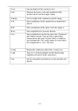
Page 16: ... target is Meas Start rangefinders to measure distance Save Start rangefinders when being under the Coordinate and Distance mode Then save the result of this measurement and name of point which is added by one automatically The result cannot be saved when the compensator is over Tilt over Comp Display the inclination tilt of the vertical axis Light Turn on or off the backlight and the illuminating...

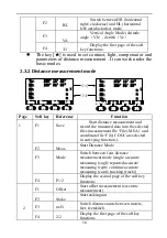
Page 17: ...F1 Save Record the measured angle to the selected file F2 0set Set the horizontal angle as 0 F3 Hset Set your desired horizontal angle by inputting but the angle should not be greater than 360 F4 1 2 Display the second page of the soft key functions 2 F1 Hold Lock the horizontal angle readings F2 Rep Repeat to measure the horizontal angle F3 V Switch between Vertical angle and slop F4 2 3 Display ...

Page 18: ...D m HD m m VD F4 F4 HD VD Page Soft key Reference Function 1 F1 Save Start distance measurement and record the measured data into the selected files measurement file File MEA and coordinate file File COO are selected in surveying function F2 Meas Start Distance Mode F3 Mode Switch between four distance measurement mode single accurate measuring sngl repeated accurate measuring rept continue accura...

Page 19: ...dinate measurement F3 Mode Switch between four distance measurement mode single accurate measurement sngl repeated accurate measuring rept continue measuring cont tracking track F4 1 3 Display the second page of the soft key functions 2 F1 Setting Set target height and instrument height F2 BSS Set coordinates of BSS back sight point and back sight angle F3 STA Set coordinates for station F4 P2 3 D...

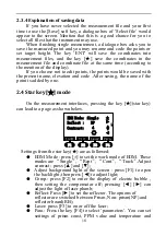
Page 20: ...esent name elevation and code After saving the name of the point is added by one 2 4 Star key mode On the measurement interfaces pressing the key star key can lead to a page as shown below Reflect NP F1 3 F4 F2 F3 Contrast 4 EDM Mode Single Settings from the star key are as followed EDM Mode press to set the work mode of EDM These modes are Single Rept Cont Track Adjust contrast press and Adjust b...

Page 21: ...After you input the temperature and pressure pressing F1 can automatically calculate the value of PPM if you are not satisfied with the value you can input and save it The interface of picture as shown below Temp Press hpa F1 3 F4 F2 F3 Prism c mm PPM ppm Signal 20 1013 0 0 ...

Page 22: ...e leveled by adjusting foot screw Our series total station can correct the error of the vertical angle reading caused by the tilt on the direction of X axis and Y axis Settings of compensator On and Off When the instrument is under unstable condition or in a windy day you should close the compensator because the vertical is unstable Only this can avoid the compensator beyond the scope of work caus...

Page 23: ...ntensity of signal is displayed in the Signal column above The minimum measurable intensity should be 1 Being less than 1 indicates that the target cannot be aimed and measured You can press any other keys to quit signal detection Range mark If the end of the signal line as shown above this mark is the distance Range identifier where R4 represents 400m L6 stands for 600m L8 stands for 800m and so ...

Page 24: ...3 5 press soft key Enter to move inserter down to the PPM column to enter the value Temp Press hpa F1 3 F4 F2 F3 Prism c mm PPM ppm Signal 20 1013 0 0 Temp Press hpa F1 3 F4 F2 F3 Prism c mm PPM ppm Signal 20 1013 0 3 3 6 2 Calculate the Atmospheric Correction out with temperature and pressure sensor First measure the temperature and pressure around the station in advance e g Temp 25 atm 1017 5 Pr...

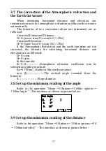
Page 25: ... corrected the formula for calculating horizontal distance and elevation are as followed D S cosα H S sinα In the formula K 0 14 Atmospheric refraction coefficient can be selected according to actual Re 6370 km Radius of the earth curvature α or β The vertical angle counted from the horizon S Slope distance 3 8 Set up the minimum reading of the angle Refer to the operation Menu 5 Options 3 Other o...

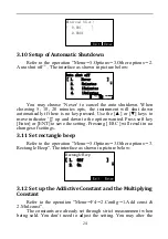
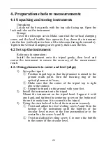
Page 26: ...pressed Use the or keys to move indicator up and down to the option wanted Press soft key Enter or ENT to save the setting Pressing ESC will result in no changes of settings 3 11 Set rectangle beep Refer to the operation Menu 5 Options 3 Other options 3 Rectangle Beep The interface as shown in picture below Rectangle Beep 1 Off 2 On 3 12 Set up the Addictive Constant and the Multiplying Constant R...

Page 27: ...o be storied in the system files of the instrument as a file form It s a good habit that selecting the measuring working files before working Please refer to the related description The file types are listed as below MEA Measurement File working for storing data COO Coordinate File used for retrieving coordinate COD Code File used for retrieving code LSH LSV Defined horizontal vertical alignment f...

Page 28: ...mmets to center and level align 1 Set up the tripod Position tripod legs so that the plummet is aimed to the ground mark point Turn the focusing ring of the optical plummet to focus Make sure that the center of the tripod top is right above the station Stamp the tripod on the ground with your feet 2 Install the instrument onto the tripod Mount the instrument on the tripod head Support it with one ...

Page 29: ...nter of the level Screw C Screw B Screw A Turn the instrument approximately 90 and adjust screw C until the bubble in the center of the level Screw C Screw B Screw A Turn around the instrument 90 again Repeat above steps until the bubble remains in the center of the plate level even though the instrument is rotated to any position 4 2 2 Using centering device to center 1 Set up the tripod Open the...

Page 30: ...ppearing this information which means the battery can support the instrument for another 4 hours The battery is lower and it s better to replace Measurement is impossible and it s necessary to replace and recharge battery Notes The working time of battery will be effected by many factors such as ambient temperature recharging time recharging and discharging times For safety we suggest you recharge...

Page 31: ...e instrument on the base Turn the clamping screw clockwise 180 to lock the instrument Then tighten the screw with a screw driver 4 6 Adjusting eyepiece lens of the telescope and aiming the target How to aim at targets only for reference 1 Aim at the bright sky with the telescope and adjust the eyepiece to focus until a sharp image of the cross wire forms 2 Aim at the target with the cross center i...

Page 32: ...4 then press 7 again SS displays in the edit box 5 Press 7 again ST displays in the edit box 6 The interval of pressing the key 7 twice is not over 0 4 seconds If over you can press or to correct it Select file MEA COO Alph List B S Enter File ST Select file MEA COO Alph List B S Enter File SU Select file MEA COO Alph List B S Enter File SS 7 7 7 Press 5 SUN displays in the edit box Select file ME...

Page 33: ... will default to Alph and can t be switched to Num The interface is as follows Station NO Pt n Clear B S Enter EO ZO m m 2 The order of the keys 1 2 3 4 5 6 3 The result is shown below Station NO Pt n Clear B S Enter EO ZO 123 456 m m m 4 Of cause you can input finally to complete the input 5 After completing the input press ENT to record the input and end the edit box Input angles Example 3 Enter...

Page 34: ...ss F4 to confirm the input or press ESC to cancel it If it is over 360 a prompt box will appear Overtop 4 8 Notice for using U disk The machine supports up to 8G U disk read and write when running the program don t insert or pull out the U disk If you pull out the U disk when the instrument checking it the subsequent operations may cause error ...

Page 35: ...oint the interface of Information appears after pressing Yes if you haven t select measured file there will be a interface of Select file MEA to let you select file which needs you the point name Pt N Code and target height T H The number of Pt N defaults to added 1 The code is input according to your need but the target height according to actual situation You can press ENT to save data to measur...

Page 36: ...the other angle unit mode input normally as shown in picture below Set HA Exit Clear B S Enter HR 123 4556 Press ENT to confirm the input or ESC TO to cancel When over 360 it will tip Overtop 5 4 Hold Function Another method to set horizontal angle Turn around the alidade to the wanted horizontal angle and press soft key Hold the turn around the alidade a and the readout of horizontal angle is hol...

Page 37: ... displayed 1st meas starts angle between two points is displayed A B Enter the interface of angleoby repetition Count Ht Exit Oset Hold Hm HR 90 00 00 90 00 00 0 Count The times of the measurement Ht The sum of angle Hm The average value of angle Aim at point A then press F1 0 set REP Angle No Yes Set 0 Press F4 Yes Count Ht Exit Oset Hold Hm HR 00 00 00 00 00 00 0 Aim at point B by horizontal mot...

Page 38: ...he steps above until the measurement times wanted If want to exit this function just press F2 Exit then press F4 Yes to return the basic measurement Notice if the angle value compared with the fist measured is over 30 the error massage will appear 5 6 Slope V Function vertical angle switched with slope V Every time you press F3 V the display mode of vertical angle will be switched each other When ...

Page 39: ...ed anticlockwise the horizon angle is decreasing 5 9 V mode Vz Zenith Mode Vh Vertical angle Mode it is 0 00 00 when the telescope is level The angle of elevation is positive and the angle of depression is negative Other instructions If the compensator is over the range of 210 then the vertical angle display box will tip you Over When setting horizontal angle which is azimuth of target point so yo...

Page 40: ...t measured file there will be a interface of Select file MEA to let you select file which needs you the point name Pt N Code and target height T H The number of Pt N defaults to added 1 The code is input according to your need but the target height according to actual situation You can press ENT to save data to measured file When the compensation value is over the instrument tips Over and the angl...

Page 41: ...t dhd is to stake out the difference between horizontal distance measured and it expected A positive result indicates that the measured horizontal distance is greater than the expectation value The lens should be moved to the instrument dvd is to stake out the difference between elevation difference measured and it expected A positive result indicates that the measured elevation difference is grea...

Page 42: ...er of instrument NC BC ZC instrument height There are three interfaces which can be switched each other by pressing F4 The functions of the first interface are Save Meas Mode The functions of the second interface are Config BSS STA The functions of the third interface are Offset S O Aver as shown in picture belown Vz HR 278 12 23 159 54 05 F1 3 F4 F2 F3 N m E m m Z Vz HR 278 12 23 159 54 05 F1 3 F...

Page 43: ...fter input the height press ENT to receive them or ESC to exit the input interface If you want to view instrument and target height just refer to this operation The input interface is as shown below I H T H T H I H m Clear B S Enter m 1 68 1 59 The range of instrument height and target height is 999 999 If the input value is over the instrument tips Overtop If you want the input value is worked wh...

Page 44: ...e point And you can press ESC to back to BSS interface STA In the second interface press F3 to enter the interface of inputting station Input station point name coordinates and instrument height STA EO NO m Clear B S Enter ZO m m List 306 254 201 345 1 254 Refer to the input of backsight Offset In the third interface press F1 to enter the offset function Offset function is designed to obtain the c...

Page 45: ...from the instrument The diagram for angle offset is as followed Instrument center Station A0 A1 Prism P HD f HD r HD r HD f HD r the horizontal distance between prism to instrument center HD f the horizontal distance between prism to instrument center When measuring the coordinate of the earth point A1 which is the projection of AO set up the height of instrument and the height of target When meas...

Page 46: ... exit 8 2 Offset Dist1 If have already known the front behind and left right offset along the direction of observation which from measured point A0 to target point A1 you may measure the coordinate of A0 through distance offset A0 A1 Target height Prism P Horizontal distance on the left or right Instrument center Station The diagram of angle offset In the menu of Offset select 2 Offset Dist1 to en...

Page 47: ...int press Save to save the coordinates of offset point press ESC to exit 8 3 Offset Dist2 It is specifically useful when the measured point is exactly on the line of the two measurable points as well as the distance between measured point and the two measuring point is known Offset distance OSD A1 A0 Prism P0 Prism P1 Instrument center Station Firstly input the offset distance If the directions of...

Page 48: ...e below Result N 0 749 Save Next P Exit E 2 026 Z 1 000 m m m If you need the coordinate of A0 you should set the height of prism as zero If you need the coordinate of A1 you should set the height of prism as the real height 8 4 Offset Plane This function is used to measure the point which can t be measured directly such as the point on the edge of the plane Firstly you should measure any three po...

Page 49: ...3 to enter the interface of Offset plane Result Offset plane Result N 12 909 HR 195 20 16 m Next P E 3 541 Save Z 3 016 Now turn around the alidade to aim at the offset point Mention that the offset point must be on the defined plane but not below the prism bar otherwise the result will not be correct The value of coordinate is being refreshed in process of aiming Press Next P to enter the offset ...

Page 50: ...interface of Offset Column Prism Offset Column Prism SD HR 181 14 01 m Meas HD Mode VD T H After measuring Offset Column Prism SD 4 570 HR 181 14 01 m Meas HD 4 575 Mode VD 1 004 T H If you want to point P0 please input its height as zero before measuring it If you want to measure P0 input the real height value then press Meas to start measure After measuring press Enter to receive the measured da...

Page 51: ...press Enter to enter the interface of Offset column L edge After aim at the right edge press Enter to enter the interface of Offset column Center as shown in picture below Offset column Center N 4 663 HR 179 59 39 m Next P E 0 117 Save Z 1 004 Press Next P to enter the next offset measurement Press Save to exit ...

Page 52: ...ill be done 9 1 Surveying Operation press MENU to enter the first page of menu then press 1 Surveying Select file MEA COO Num List B S Enter File AAA 1 Menu 1 Surveying 1 2 2 Stake 3 Fileman 4 Program 5 Options P1 Press F4 to enter the interface of Surveying Surveying 1 Station 2 Setup BSS 3 Meas 4 Survey Config 9 1 1 Operation 1 Select file for surveying to save the surveying data 2 Set station i...

Page 53: ...r the interface of file list You can press F1 F4 to create view search and delete file AAA MEA MEA ACB MEA New MEA Search Info Del TEST MEA 123 MEA MEA MEA Pressing the key of or to make the file list to stroll up and down pressing or to make the pages turning selecting a file then pressing ENT calling a file successfully Entering into the function of surveying after setting the measurement file a...

Page 54: ... 1 Set backsight point by coordinate in memory 2 Input the coordinate of backsight point directly 3 Input the orientation angle directly 9 1 3 1 Example for set station The operations of set station by using the data in memory 1 Enter the interface of Set STA with original data displayed Setup STA STA Save Search Input STA Code I H S0 1 000 m 2 Press the key F4 STA Surveying Setup STA Coord List I...

Page 55: ...t to the interface of Setup STA Setup STA STA Save Search Input STA Code I H PT1 1 000 m 6 Press to move the to Code column Setup STA STA Save List Input STA Code I H PT1 1 000 m 7 Press F1 to input code then press F4 to confirm it Setup STA STA Save List Input STA Code I H PT1 TREE 1 000 m 8 Move the to I H column then input the instrument height and press F4 Enter Setup STA STA Save Input STA Co...

Page 56: ...gle must be confirmed by measuring You can save the data of orientation angle of backsight point by the following method 1 Enter the interface of BSS Setup BSS BBS Meas Search Input BBS Code I H 0 1 000 m 2 The screen displays the data set last time You can press F4 BSS Surveying Setup BBS NE AZ List Input Enter Pt n 1 3 Press F1 Input Surveying Setup BBS Num Input Enter Pt n PT2 4 Input point nam...

Page 57: ... I H PT2 1 000 m 6 Input Code and target height T H Setup BSS BBS Meas List Input BBS Code I H PT2 1 000 m 7 Press F3 Meas Setup BSS BBS Coord SD Angle Code I H PT2 1 000 m 8 Aim at the backsight point and select a key of measurement mode For example press F2 SD then measure the backsight point VZ HR 222 45 24 No Enter Yes SD 3 363 VD 3 078 m m HD 87 33 43 1 354 m 9 Press F4 Yes to finish setting ...

Page 58: ...ss Enter to input code Meas Pt n Num Search Input Enter Code T H 3 1 000 m Meas Pt n Num B S Enter Code T H 3 TREE 1 000 m F4 Enter List 3 Input target height I H then press Enter Meas Pt n Code T H 3 TREE 1 000 m Meas Pt n Code T H 3 TREE 1 000 m F4 4 Press F3 Meas here there are four methods for you to select which are Angle Dist Coord Offset as shown in picture below Meas Pt n Code T H 3 TREE 1...

Page 59: ...t methods 8 Finishing measurement the data will be saved and youcan press ESC to exit 9 2Staking out Staking out is to find the earth point for the designing point The required process of staking out is as followed 1 You may select files for staking out The files can call the coordinates of station STA backsight BSS and the stakeout point etc 2 Setup station STA 3 Setup backsight BSS to determine ...

Page 60: ...points Two methods for staking out to be selected 1 Retrieve the coordinates in the memory by point nane 2 Input coordinates directly Example for retrieving coordinates to stake out 1 In the first page of staking out press 3 Stake out S 0 Stake out Coord List Input Enter Pt n 3 S O 1 Setup STA 1 2 2 Setup BBS 3 Stake out P1 2 Press F1 Input to input point name Pt n then press Enter S O Stake out B...

Page 61: ... Coord 6 The rotation angle of the alidade will be calculated by the instrument HR dHR T H Mode Meas Next P HD m dHD m dZ 251 24 23 1 59 29 m HR dHR T H Mode Meas Next P dN m dE m dZ 251 24 23 1 59 29 m Dist Coord HR measured angle dHR the rotation angle when the instrument aiming at stake out point When dHR 0 00 00 it means you haves found the direction pf stake out point 7 Rotate the instrument ...

Page 62: ...dZ are zero the staking out is completed HR dHR T H Mode Meas Next P HD m dHD m dZ 252 23 52 0 00 00 3 473 0 000 0 000 m HR dHR T H Mode Meas Next P dN m dE m dZ 252 23 52 0 00 00 0 000 0 000 0 000 m Dist Coord 9 Press F4 Next P to enter the next point stake out Then the last stake out point will be displayed If the last point name is number then the next point name will be added 1 S O Stake out B...

Page 63: ...s F4 Meas to start measurement PolarCoord Meas HR Measuring N m E m Z 252 24 22 Sngl m 4 After measuring the measured coordinates is displayed You can press F4 Yes to save the measured value and the point name will be added 1 PolarCoord Meas HR No Enter Yes N m E m Z 252 24 21 1 532 0 486 0 174 m Yes PolarCoord Meas Pt n B S Meas Code T H PL2 1 1 000 m List Num ...

Page 64: ...nt Measure at least three known points 1 Enter the second interface of staking out and press F2 Resection S O 1 PolarCoord Meas 2 2 2 Resection P2 2 Input the new point name Pt n code and target height I H New Pt Pt n B S Enter Code T H 1 1 1 000 m 3 Press F1 Input to input point 1 Here you can retrieve points and press F4 Resection NO 1 Num List B S Enter Pt n 1 Enter Resection NO 1 Coord List In...

Page 65: ...m m 5 Press F4 Yes to enter the interface of Input T H After input the target height T H press F4 Input T H Clear B S Enter T H 1 000 6 Aim at the known point 1 press F3 Angle or F4 Dist Press F4 Dist for example VZ HR SD m T H No 1 2 09 30 102 09 30 1 000 m Dist Angle Aim at BS 7 Start measuring VZ Measuring HR SD m T H No 1 2 09 30 102 09 30 Sgnl 1 000 m 8 Enter the input interface of point 2 ...

Page 66: ...Press F1 to measure other known points which are at most five points Resection NO 3 Num List B S Enter Pt n 3 11 Press points 3 according to the step 3 step 5 VZ Next P Calc HR SD m T H No 4 52 09 30 102 00 30 10 953 1 000 m 12 You can press F4 Calc to check the result of resection and the standard deviations of the coordinates is displayed Unit mm St D D n Coord D e D z 4 6 1 mm mm mm ...

Page 67: ...leman 1 Update 2 2 P2 2 About 9 3 1 File Dialogbox The operations of Create a new file delete file view file and so on are called file dialogbox These operations involve the file list Select File Dialogbox to enter the interface of Select Disk as shown in picture below Select disk 1 FLASH 2 USB Enter Exit After selecting the disk press Enter to enter the interface of file type as shown in picture ...

Page 68: ...t back to the file list interface Info Name F01 MEA Exit Mode File MEA Size 449 B Data 23 2 Search file Press Search to enter the interface of Search as shown in picture below After input the file name press ENT If found it then back to the file list with the cursor at the file name or tips Has t file Search Num B S Enter Name 2 3 Create new file Press New to enter the interface of file type then ...

Page 69: ...e When viewing the file data you can just view the measurement file coordinate file and code file You can view the data of horizontal and vertical alignment file in the road function Select a measurement file in the file list and press ENT to display the data list as shown in picture below The left side of list is point name and right is data type ST1 STA BS01 Del BS Search View S1 S2 ANG DIST S3 ...

Page 70: ...e system searches the data from the first piece all name matched If searching it the cursor will be at the point or will tip and back to the first piece data press Del to enter the interface of Del if select Yes the data you selected will be deleted or press Exit back to the data list 9 3 2 Import As the format of file in the instrument is binary the External data must be imported to instrument Th...

Page 71: ...r selecting file press Enter to enter the interface of importing Baud Slow Fast Import File No 115200 123 COO The only column that can be set is the Baud The Baud available are 2400 4800 9600 19200 38400 57600 115200 with respect to the RS232C serial communication bus The bauds can be set with soft keys Fast and Slow Usually 115200 Baud is adequate for importing Import Import data The process of i...

Page 72: ...w Type of import 1 Import from PC 2 Import from USB Press 2 to enter the interface of Import data interface as shown in picture below Import data 1 Receive COO 2 Receive COD As an example of importing coordinate data press 1 yo enter the interface of Select file The files in the directory of PROJECT in U disk will be read Select file SUA TXT Quit Enter CODE TXT COOR TXT Press or to select coordina...

Page 73: ...pressing Enter there is Transforming displaying and the data in the U disk will be saved in to the instrument until finishing importing 9 3 3 Export Select Fileman 3 Export as shown in picture below Transmission 1 Export to PC 2 Export to USB 3 Import from Mini 9 3 3 1 Export to PC Select 1 to enter the interface of Export data as shown in picture below Export data 1 Send MEA 2 Send COO Taking an ...

Page 74: ...or other can recognize SSS format Select format 2 SSS 1 Sunway After selecting the format enter the interface of exporting as shown in the picture below Baud Slow Fast Export File No 115200 1 MEA The operation of key functions which are Fast Slow you can refer to the import You may be careful that the export file must be measurement and coordinate or can t be exported When exporting file the compu...

Page 75: ...Here input the file name for saving the exported data which will be saved in the directory of PROJECT in the U disk If there is a same name file in the Udisk it will tip After you pressing F4 the measurement file will be read and transferred to be saved with text format in the U disk The export of coordinate file refers to it of measurement file 9 3 3 3 Export with Mini USB port Connect the MinUSB...

Page 76: ...he following functions must be carried out under the guidance of professionals if the operation is wrong it may lead to the instrument can t work properly This function is for you to upgrade the software of the instrument Press 1 on the second page of Fileman to enter the interface of updating as shown in picture below B S Enter PIN Clear 1 Input PIN Contact NWI for update PIN then press ENT with ...

Page 77: ... cautious when updating As soon as you choose to update the instrument will enter updating mode If pressing key 3 under the page shown below the previous program may be resumed 4 Press key 1 on the keyboard The instrument enters the waiting state for sending programs After the state click Send File on the computer ...

Page 78: ...ion menu again You can press 5 to update boot image and press 6 to update language 7 After update program boot image language press 3 to end the update and press power button to turn on the instrument to run the updated program 9 4 Program The operation in the menu of staking out Press the key of MENU the instrument will enter into the mode of Menu 1 2 Press the key of 4 Program ...

Page 79: ...d at the target point Under REM mode you can place the prism on any point along the plumb line of the target point to obtain the height of target VD Prism height prism P Target point C There are two modes for REM measurement Input TH and without TH You can select Input TH mode when you need the altitude from ground to target otherwise without TH when you need the altitude from any reference point ...

Page 80: ...ays the elevation difference from the ground to the target point After measurement you may choose from three opts T H to alter the target height Hdist to re measure horizontal distance ESC to quit REM measurement You can choice according to the actual usage 9 4 1 2 Without T H After select this mode enter the interface of REM Prism REM Prism VZ Mode Meas Enter HR HD 77 18 33 169 11 14 m Aim at the...

Page 81: ...EM Altitude VZ SetVA HR VD 77 18 33 169 11 14 1 657 m HD After the measurement you have three opts Set VA to re enter the REM Altitude page HDist to re measure the horizontal distance ESC to quit REM measurement 9 4 2 Resection For the following steps see reference in chapter 9 2 3 Resection 9 4 3 MLM dHD dVD dSD Prism B Prism A Prism C Instrument Diagram of MLM Measure the horizontal distance dHD...

Page 82: ...Step 2 MLM A B A C Step 2 VZ Coord T H Meas Mode HR HD 72 32 12 132 08 13 m 3 Get the coordinates by the same way of the Step 1 then press ENT to enter the interface of MLM A B A C Result The result displayed is the measurement from first point to second point If you press Next P you will repeat the operations of MLM A B A C Step2 and MLM A B A C Result and can get the measurement result of first ...

Page 83: ...nt whose input method is same as the it of backsight point Press ENT to end inputting and enter the measurement interface of Coord Z No 1 Coord Z No 1 HR 170 12 23 Meas Enter HD VD m SD m m Mode 3 Press Meas to start measuring After measuring the measured value will be displayed and you can press Enter to confirm this measurement then the keys Next Mode and Calc appears You can press Next to conti...

Page 84: ...point information here you can retrieve point Point Area N B S E m Z m 0 643 0 156 0 624 m Clear List Enter 3 After pressing Enter the point will be listed in the area measurement list as shown in picture below Area Del Meas Input Pt01 0 643 0 156 4 The same way above input the other points which will be listed to area measurement list Area Del Meas Input Pt01 0 643 0 156 Pt02 1 000 5 000 Pt03 100...

Page 85: ... of baseline distance Y of the prism point deviation from baseline and altitude difference Z of the prism point deviation from the starting point of baseline The preparation before measurement setting up the instrument height the target height and defining the baseline Define base line In the interface of project press 2 2 Baseline to enter the interface of Setup Baseline Retrieve base line point ...

Page 86: ...3 Project 3 Project to start projection measurement Projection In the project menu press 3 project to enter the interface of Project Survey press Meas to start measuring After the measurement the deviated length X distance Y and altitude difference Z are displayed on the screen Project Survey SD 166 40 39 Meas Turn HD VD HR 0 754 T H 0 754 0 002 m Project Survey X 166 40 39 Meas Turn Y Z HR 0 300 ...

Page 87: ... enter the interface of Other options Other options 1 Mini Angle 1 2 2 Auto shut off 3 Rectangle Beep P1 Other options 1 K option 2 2 2 Beep P2 3 Miniread dist Taking EDM for example the interface as shown below EDM Mode 1 Single Enter 2 Rept 3 Cont 4 Track Exit Press or to move the to the options needed then press Enter to receive the select and save it to system file After shut on the instrument...

Page 88: ... right Following the same steps the instrument will then calculate the index error and display it Now press ENT to save the index error calibration done otherwise press ESC to quit previous I E remains Note If there is no special requirement the compensator should be turned on before Index error correction 9 6 2 Calibrate TILT X Before compensating for the compensator make sure that the indicator ...

Page 89: ...ew A to aim at the target precisely 5 Aim at the target F2 in the collimator with reverse telescope and record the current vertical angle as V1 6 Set the vertical angle to V1 3 with the help of the vertical tangent screw Adjust the screw A to aim at the target precisely and press ENT to confirm after a stable readout appears 7 Set the vertical angle to V1 3 with the help of the vertical tangent sc...

Page 90: ...ack to the original direction 4 Set the vertical angle to V0 with the help of vertical tangent screw Adjust the screw A to aim at the target precisely 5 Aim at the target F2 in the collimator with reverse telescope and record the current vertical angle as V1 6 Set the vertical angle to V1 3 with the help of the vertical tangent screw Adjust the screw A to aim at the target precisely Then turn the ...

Page 91: ...ditive constant Add const is same as it of multiplication constant Mul const Here take additive constant for example In the Config menu interface press 1 to enter the interface of inputting additive constant as shown in the picture below B S Enter Add C 6 mm After inputting press Enter with a prompt Saved appearing then exit the interface 9 8 Select code file In the second page of Menu press 3 Sel...

Page 92: ...NT to save the scale gird and exit this interface Exceptions if the scale value is less than 0 99 or greater than 1 01 it indicates that the altitude input is error and you must re input it If you pressing ESC the scale will not saved 9 10 Communication If the instrument equipped Bluetooth select 5 Communication on the second page of Menu Press 5 on the second page of Menu to enter the interface o...

Page 93: ...ening the LS file Stake out road Resume H curve or Resume V curve 10 1 Inputting Roadway The input of road design is divided two parts one of which is the input horizontal alignment and the other is vertical alignment The input data will be saved in the selected files whose maximum number of element is 21 but the number of intersection cannot be greater than 20 10 1 1 Horizontal alignment The inpu...

Page 94: ...ter N E Mark Note Do not define the length as 0 which indicates ending the alignment Input Line Define H Line Clear B S Enter AZ 0 0000 Len Input Circle Define H Circle Clear B S Enter R Len Arc length Radius The value of Radius R can be negative The positive direction is the right direction along the designed roadway and the left is negative The Len refers to Arc length Input Spiral ...

Page 95: ...0 03CI 10100 000 04LI 10118 000 10000 000 mileage Press Save to save the input data Press View to display the input Edit Spiral PgUp Edit PgDn R 255 000 Len 100 000 If you find some of them are wrong you can press Edit to modify You can press PgUp Page up or PgDn Page down to check the inputs one by one You can press Add to continue inputting after pressing ESC 10 1 1 2 Intersection method After c...

Page 96: ... 1 Press ENT to input the next intersection point after inputting If the N E Z column s are null the key ENT is invalid After finishing inputting press ESC to exit then enter the interface of List of H curve Press View then you can view the data input and edit data Press Add then you can continue alignment Repeat the steps above until complete the input After complete the horizontal alignment retu...

Page 97: ...eight Len Then you can input the Mark Height and Len for other points in order Finally press ESC to end inputting and enter the interface of List of V curve The operations of the key about Save View and Add refer to element method After finishing defining H and V curve the last input will be saved in the buffer cache and will be erased when shutting the instrument down The data can be used to stak...

Page 98: ...t deviation and L R dV left and right altitude difference Left Right dV 5 Then select center left and right mileage to stake out 6 You may choose Dist polar coordinates or Coord to stake out 10 2 1 Selecting Roadway File There are two routes to select roadway file LS file 1 Roadway menu Open shape file 2 Roadway menu Stake out road Select file Both ways above lead to page of select file You can se...

Page 99: ...terface if all deviations are zero Roadway Center Mark Edit S O offset VD 0 000 0 000 1 700 T H 0 000 The soft key functions under this page are as followed Key Explanation F1 Setup any mileage and target height F2 No use in this page F3 calculate the coordinate of the staked out point first Current mileage minus space to obtain new mileage Current mileage plus space to obtain new mileage Switch b...

Page 100: ...inate file Press Enter to enter the interface of Roadway Calc which displays the azimuth angle and horizontal distance Roadway Calc Coord Dist HR HD 68 48 31 354 456 You can select F1 Dist to stake out by polar coordinate or F3 Coord to stake out by coordinate which refer to 9 2 2 Polar Coordinates and 9 2 1 Stake out The key ESC in every interface above can return to the interface of Roadway Cent...

Page 101: ...o the center 2 Turn the instrument 180 to check that whether the bubble is in the center If the bubble is not centered repeat step 1 until the bubble is in center 3 Turn the instrument 90 and use the third foot screw to adjust the bubble to the center 4 Repeat the steps of checkout and calibration until the bubble in the center in every direction 11 2 Circular Level Check After the level tube is c...

Page 102: ...re the crosshair doesn t need to calibrate If point A deviate from vertical line center as the right picture the crosshair is slant so need to calibrate the reticle 8 8 A A 8 8 A A Calibration 1 First take down the reticle cover between telescope eyepiece and focusing hand wheel and you can see four fixed screw of the reticle bed sees attached figure 2 Unscrew the three fixed screw evenly with scr...

Page 103: ...read the horizontal angle e g HA R 190 13 40 4 If 2C L R 180 30 20 the instrument need to be calibrated Calibration 1 Use the horizontal slow motion knob to adjust the horizontal angle to the right reading which has eliminated the C R C 190 13 40 15 190 13 25 2 Take down the reticle bed cover between the telescope eyepiece and focusing hand wheel adjust the calibration screw of the crosshair on th...

Page 104: ...rotate feet X to 10 mm around in one direction the display of the vertical angle will change from changing until disappear to appear Tilt over correspondingly it indicate that the dip Angle of the vertical axis is bigger than 3 beyond the range of vertical plate compensator design When rotating the feet spiral recovery in the opposite direction the instrument shows vertical Angle again if you can ...

Page 105: ...w the instrument 2 Adjust the focal length of the optical plummet for the optical plummet or press key to switch on laser plummet move the white paper to make the cross in the center in the field of view or laser flare 3 Turn the feet screw make the center mark of the plummet coincide with the cross center 4 Rotate alidade every turn of 90 observe the contact ratio of the optical plummet and cross...

Page 106: ...nd level the instrument mark three points A B C in the same line their interval is 50m and set up the reflection prism accurately 2 After setting the temperature and atmospheric pressure of the instrument measure the horizontal distance of A B and AC accurately 3 Place the instrument at point B then centering it accurately to measure the horizontal distance of BC precisely 4 Obtain the distance me...

Page 107: ...curately 3 Observe the maximum signal value through starkey Para Signal find the center of the launch axis 4 Check whether the telescope crosshair center coincide with the emission photoelectricity axis center if they coincide on the whole we can say it qualified Calibration If the telescope crosshair center deviates from emission photoelectricity axis center largely send it to professional repair...

Page 108: ...ffset between the red laser point and the reflector crosshair center you can observe this above the telescope or at the side face of reflector If laser center coincide with the crosshair center it indicates that the adjustment meet required accuracy If the offset between the point position and the mark of crosshair is out of limit it will need to be sent to professional department for adjustment I...

Page 109: ...method Absolute encoder Minimum reading 1 Distance measurement IR Range Single prism km 3 Triple prism km 5 No prism1 m 400 600 Time Repeated s 2 first 3 Tracking s 0 8 Minimum display mm 0 1 Accuracy Prism mm 2 2 10 6 D No prism 3 2 10 6 D Tilt compensator Compensation method Biaxial type Compensation range 3 Communication Port RS232C U disk interface Yes Bluetooth Yes Temperature and pressure se...

Page 110: ...bular level 2 mm 30 Round level 2 mm 8 Built in application Support Battery supply Type Rechargeable High energy lithium battery Voltage V 7 4 Power W 2 2 Battery capacity mAh 3000 Working duration Angle h 18 Dist Angle h 8 At 20 C constant measuring mode 1 Refers to good weather conditions visibility is not less than 30km the goal of KODAK CAT NO E1527795 90 of reflecting surface ...

Page 111: ...irst line record type name elevation code Such as STA refers to station point BKB refers to back sight Angle data BS refers to back sight SC refers to coordinate data SD refers to distance measurement data SA refers to Angle measurement data The second line information data types data records Such as NEZ refers that the following data are coordinates with the order NEZ ENZ refers that the followin...

Page 112: ... the distance unit is mm Command frame list means connection 1 Check communication Ask STX T C CR Respond X_ON 2 Set the horizontal angle Ask STX S A HHHHHHH CR Respond X_ON HHHHHHH indicates azimuth angle Example 120 43 55 can be explained 1204355 3 Read angle data Ask STX R A CR Respond STX R A HHHHHHH VVVVVVV CR HHHHHHH is azimuth angle VVVVVVV is vertical angle 4 Read distance and angle data A...

Page 113: ...ADDRESS 69 King Street Dover NJ 07801 USA ...

Reviews: