


7
TOWER SYSTEM
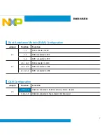
Boot Assistance Module (BAM) Configuration
Jumper
Position
Function
J3
1-2
FAB connected to VDD
3-4
ABS0 connected to VDD
5-6
ABS1 connected to VDD
J4
J4-1, J3-2
FAB connected to GND
J4-2, J3-4
ABS0 connected to GND
J4-3, J3-6
ABS1 connected to GND
CAN Configuration
Jumper
Position
Function
J6
2-4 & 1-3
CAN0 is connected to CAN0 module on primary elevator
4-6 & 3-5
CAN0 is connected to the on-board CAN transceiver
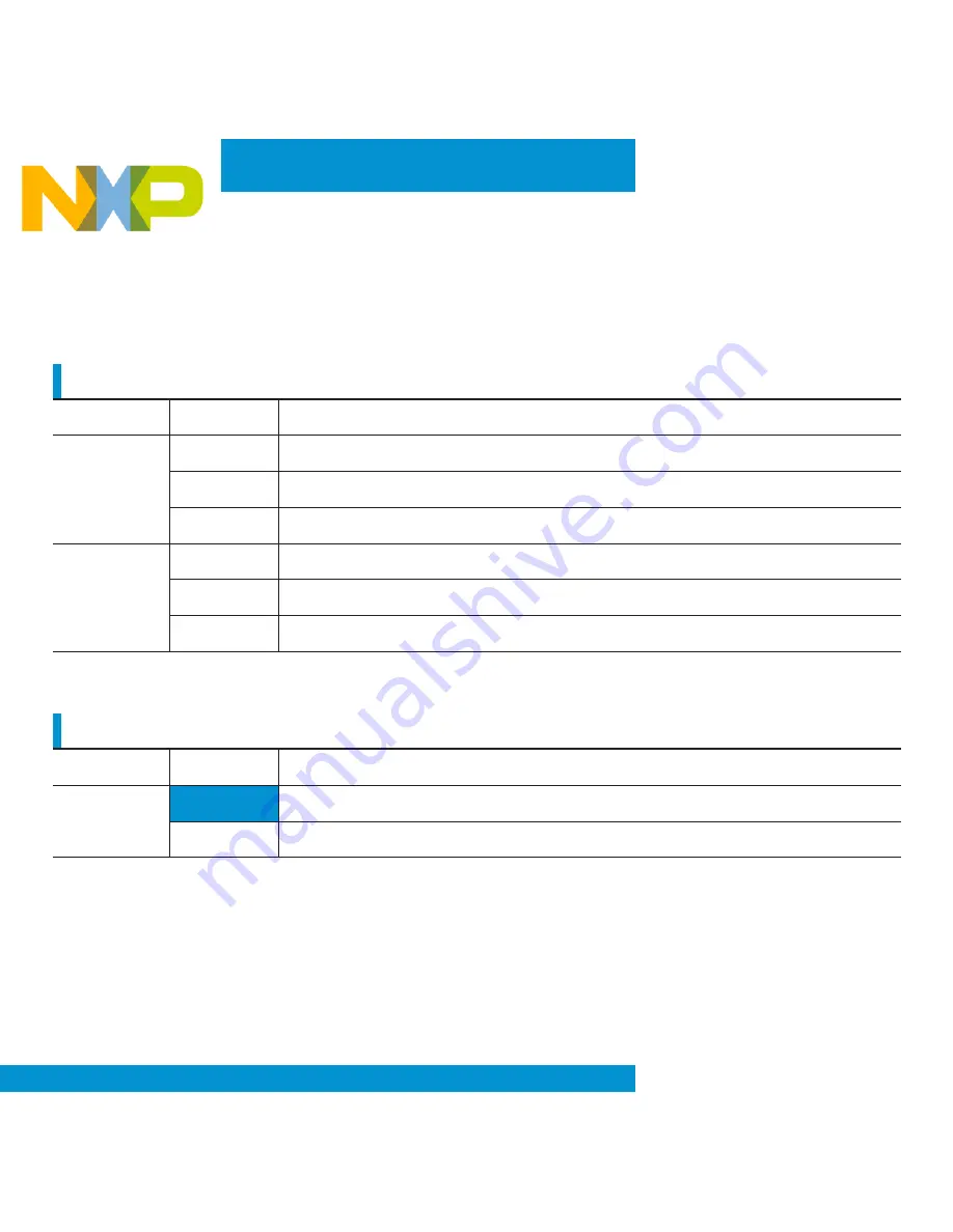
General Jumper Configuration
Jumper
Function
J15
Enable/Disable CAN terminator resistor
J10
Enable/Disable potentiometer
J12
Enable/Disable OSJTAG interface bootloader mode
J19
Enable/Disable RS485 half duplex control lines
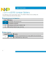
Power Supply
Jumper
Position
Function
J5
1-2
3.3 voltage is coming directly from the 3.3 voltage regulator on the primary elevator
2-3
3.3 voltage provided by on-board circuitry


