


NZXT. 4
Before Beginning..
For safety issues, it is highly recommended that all users wear
gloves during installation. Also, if you have any questions during
installation, please send an email to
service@nzxt.com
before
proceeding.
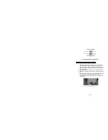
Power Supply Installation
Please refer to the case interior infrastructure and secure the power
supply at the back of the case by using the screws provided.
Motherboard Installation
The Guardian 921 supports the following motherboard: ATX, BABY
AT, MINI ATX, and MICRO ATX. The Index for the standoff holes
are as follows. (Imprinted on the motherboard tray are serial
numbers that match certain motherboards)
A1~A9 ATX
B1~B9 BABY AT
M1~M9 MINI ATX
U1~U7 MICRO ATX
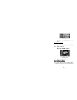
In order to install your motherboard go through the following steps:
1. Lay your case down so you can see the drive cages and the
standoff holes on the motherboard tray.
2. Take your motherboard and match the standoff holes.
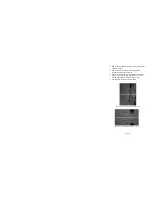
3. Remembering which standoff holes your motherboard
needs, proceed to screw the brass standoffs onto the
NOTE
: CPU, RAM and any peripheral installation are not
included in this manual. Please refer to your motherboard manual
for related mounting instructions and troubleshooting.
Summary of Contents for GUARDIAN 921
Page 1: ...GUARDIAN 921 User s manual...
Page 2: ......


