background image


NZXT. 6 

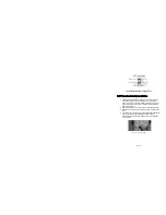
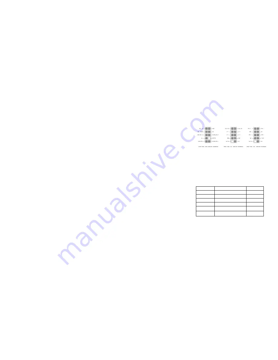
Audio Port Installation


1.  Please first refer to your motherboard manual and match the 

labels on the audio port connectors with your motherboard in 
order to install.  

2.  The green input is the speaker input and the pink input is the 

microphone input, these inputs are located at the left side of 
your front panel. 


Case Pins  


Signal Description     


ASUS© Pins 

MIC-IN 

Front Microphone input Signal 

MIC2 

MIC-POWER Front 

Microphone Power 

MICPWR 

GROUND 

Front Audio Ground 

AGND 

L-OUT 

Front Left Channel Audio Signal 

Line out_L 

R-OUT 

Front Right Channel Audio Signal 

Line out_R 

L-RET 

Rear Left Channel Audio Signal 

BLINE Line 
out_L 

R-RET 

Rear Right Channel Audio Signal 

BLINE Line 
out_R 

Summary of Contents for GUARDIAN 921

Page 1: ...GUARDIAN 921 User s manual...

Page 2: ......

Page 3: ...the market today Since then we have stayed true to our goal which was to continuously provide innovative next generation products With every product we are still breaking more boundaries and limits O...

Page 4: ...ions 3 Before Beginning 4 Power Supply Installation 4 Motherboard Installation 4 LED Power and Reset Installation 5 USB Audio Installation 5 5 25 Screwless Drive Bay Installation 7 Hard Drive Installa...

Page 5: ...ain takes design cues from gaming culture with elegant curves and a newly designed clear side panel allowing the user to see the components inside Cooling with low noise The Guardian 921 comes standar...

Page 6: ...ATX The Index for the standoff holes are as follows Imprinted on the motherboard tray are serial numbers that match certain motherboards A1 A9 ATX B1 B9 BABY AT M1 M9 MINI ATX U1 U7 MICRO ATX In orde...

Page 7: ...ed inside the front door Blue White 2 Connect the Power Switch pin labeled P LED to the PWR connector on the motherboard The power switch is the chrome piece on the front panel Green White 3 Connect t...

Page 8: ...icrophone input these inputs are located at the left side of your front panel Case Pins Signal Description ASUS Pins MIC IN Front Microphone input Signal MIC2 MIC POWER Front Microphone Power MICPWR G...

Page 9: ...hole of your drive with the drive bay holder and make sure the device is where you want it 2 Remove the plastic 5 25 cover in the designated drive bay 3 Slide the 5 25 device into the drive bay from...

Page 10: ...vices such as hard drives Three of the four drives run on screwless slides Please follow the instructions below 1 Attach the slides onto the side of the device Hard Drive Sliding into Place 2 Slide th...

Page 11: ...bscrews at the rear of the case 3 Remove the Hard Drive cage by unscrewing first the two screws to the left of the cage and then the two screws located at the bottom of the case Figure 1 2 4 After rem...

Page 12: ...tact service nzxt com along with a detailed explanation of your problem and your proof of purchase You may inquire about replacement parts at rma nzxt com Thank you again for purchasing an NZXT case I...

Reviews: