Page
5
of
22
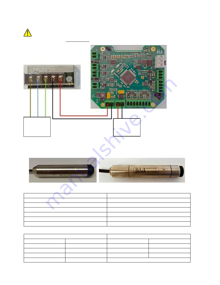
Power Input / Output Connections
WARNING
Before applying the power,
DOUBLE CHECK
all the connections to the inputs and outputs.
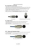
Tank Level Probes
Standard Probes Legacy Probes
Standard Probes
Legacy Probes
A12 / 3m = 3m Sensor with 10m of cable
A / B29 = 1.0m Sensor with 4m of cable
A14 / 5m = 5m Sensor with 10m cable
A / B30 = 1.5m Sensor with 4m of cable
A16 / 10m = 10m Sensor with 10m cable
A / B23 = 3.0m Sensor with 6m of cable
A18 / 20m = 20m Sensor with 20m cable
A / B25 = 5.0m Sensor with 7m of cable
A20 / 30m = 30m sensor with 30m cable
A / B26 = 7.0m Sensor with 10m of cable
A / B27 = 10.0m Sensor with 12m of cable
Standard Probes
–
Wire Colours
Legacy Probes
–
Wire Colours
Brown
+V
Red
+V
Green
Signal
Black
Signal
White
Not Used
Blue
Tempe
Yellow
Temperature -
Legacy A Series Probes Do Not Have Temperature
100
–
240v AC
Maximum
Current - 0.7A
Power Pass
through from
Power Supply
Summary of Contents for T4020
Page 14: ...Page 13 of 22 Appendix 1 T5020 Wiring Diagram ...
Page 15: ...Page 14 of 22 Appendix 2 Modbus Register Table ...
Page 16: ...Page 15 of 22 ...
Page 17: ...Page 16 of 22 ...
Page 18: ...Page 17 of 22 ...


