Page
7
of
22
Scroll down and there will be a folder
Ports (COM & LPT)
. I
t should show the USB Serial Port with the Com
port it is attached to, in this case, (
COM7
), this will vary on whatever computer the programmer is attached.
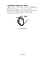
This is the figure that is entered in the T4020 Configuration Software. The communications lead RED LED
should flash when you try to connect the USB programmer to show the address for the lead is correct.
Connect the Programmer to the T5020 Gauge as shown in Page 4.
Configurator Software.
Next step is to open the T4020 Configuration Software.
Click on the
File
tab. On the drop down menu, click on the
Program Settings
tab.
Summary of Contents for T4020
Page 14: ...Page 13 of 22 Appendix 1 T5020 Wiring Diagram ...
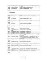
Page 15: ...Page 14 of 22 Appendix 2 Modbus Register Table ...
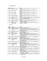
Page 16: ...Page 15 of 22 ...
Page 17: ...Page 16 of 22 ...
Page 18: ...Page 17 of 22 ...


