background image

22

Connect battery leads to glowplug.

Check that the needle-valve is closed. (Do 
not overtighten.) Now open the needle-
valve counter-clockwise 2 turns to the 
starting setting.

3.

4.

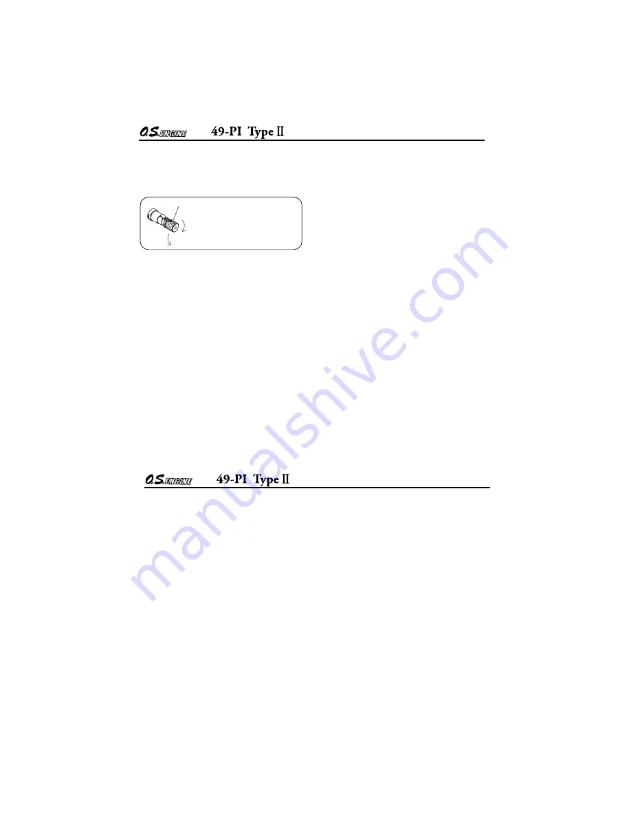
Turn needle-valve clockwise to close 
(for leaner mixture)

Turn needle-valve counter-clockwise 
to open (for richer mixture)

Mark

Close

Open

5.

6.

Bring electric starter into contact with 
spinner-nut or spinner and depress starter 
Switch for one to two seconds. Repeat if 
necessary. When the engine starts, 
withdraw the starter immediately.

7. 

Open the throttle fully and deliver fuel to the 
carburetor by applying an electric starter for 
a very short time.

Set the throttle valve at 1/3 open from fully 
closed position and connect battery leads to 
glowplug.

When the engine is started, open the throttle 
slowly to full open. Run the engine 5~6 
seconds without changing needle-valve 
position. If the r.p.m. lower due to rich 
mixture, close the needle-valve a little.

8. 

Now disconnect battery leads and close the 
needle-valve slowly one click at a time.  
Abrupt closing may stop the engine specially 
when the engine is new and running-in is 
incomplete.

9. 

23

Attention :
Do not choke the carburetor air intake when 
applying the starter.  This could cause an 
excessive amount of fuel to be drawn into the 
cylinder which may initiate an hydraulic lock 
and damage the engine.
If the engine does not start within 10 repeat 
applications of the starter, remove the glow-
plug, check that it glows brightly and that the 
cylinder is not flooded with fuel. (To eject 
excess fuel, close needle-valve and apply 
starter with glowplug removed.) Then try again.

Note:
Make sure that the throttle linkage is made 
so that the throttle is fully closed when the 
throttle lever as well as trim lever on the 
transmitter are fully pulled down.

How to stop the engine
Pull down the throttle lever and trim lever on 
the transmitter fully.

VERY IMPORTANT!
Before being operated at full power (i.e. at full-
throttle and with the needle-valve closed to its 
optimum setting) the engine must be adequately 
run-in, otherwise there is a danger of it becoming 
overheated and damaged. 

Summary of Contents for 49-PI II

Page 1: ... suggested that any instructions supplied with the aircraft radio control equipment etc are accessible for checking at the same time 1 2 6 7 9 11 14 15 16 32 33 17 30 31 18 20 34 21 25 26 27 28 29 35 36 10 CONTENTS SAFETY INSTRUCTIONS AND WARNINGS ABOUT YOUR O S ENGINE ABOUT THE ENGINE BASIC ENGINE PARTS BEFORE STARTING INSTALLATION OF THE STANDARD ACCESSORIES MIXTURE CONTROLS GLOWPLUG INSTALLATIO...

Page 2: ...sonous Do not allow it to come into contact with the eyes or mouth Always store it in a clearly marked container and out of the reach of children Never operate your engine in an en closed space Model engines like auto mobile engines exhaust deadly carbon monoxide Run your engine only in an open area Model engines generate considerable heat Do not touch any part of your engine until it has cooled C...

Page 3: ...s check the tightness of the propeller nut and retighten it if necessary before restarting the engine Also check the tightness of all the screws and nuts before restarting the engine If you install a spinner make sure that it is a precision made product and that the slots for the propeller blades do not cut into the blade roots and weaken them Preferably use an electric starter The wearing of safe...

Page 4: ...er this if you wish to avoid the risk of a painfully rapped knuckle 7 The O S rotary combustion engine based on NSU Wankel System was the world s first production model engine of the rotary piston type as invented by Felix Wankel in 1957 and produced by NSU Wankel in 1959 This highly successful application of the NSU Wankel System to a power unit of miniature proportions has only been made possibl...

Page 5: ...e Also handling of this engine is some what different from that of two stroke and four stroke engines 1 2 9 When the engine is enclosed in a cowl be sure to make ventilation holes outlet hole Should be lager than inlet hole or the engine will overheat which results in poor engine running or seizing in worst case Prime the engine fairly liberally with fuel and turn the propeller more than 3 turns s...

Page 6: ...se made manual or electric fuel pumps may be used to transfer fuel directly from your fuel container to the fuel tank FUEL PUMP Manual Electric FUEL Model engine fuel is poisonous Do not allow it to come into contact with the eyes or mouth Always store it in a clearly marked container and out of the reach of children Model engine fuel is also highly flammable Keep it away from open flame excessive...

Page 7: ...tank for helicopter as it has small dia of 10mm 13 9x6 7 10x4 6 11x4 5 SIZE DxP Since the 55AX is intended to be started with an electric starter the addition of a spinner assembly for centering the starter sleeve is desirable Use a heavy duty well balanced spinner either of metal or plastic Spinner A fuel tank of approximately 320cc capacity is suggested This allows around 10 12 minutes flying ti...

Page 8: ...0 size engines Guide weight 2 000 2 500g Model 15 STANDARD ACCESSOIES Glow Plug Type F installed on the engine Non Bubble Weight S RE 2010 Silencer Assembly Silencer Retaining Screw INSTALLING THE GLOWPLUG Install washer on glowplug and insert carefully into rotor housing making sure that it is not cross threaded before tightening firmly INSTALLATION OF THE STANDARD ACCESSORIES Silencer Body Press...

Page 9: ...ust be regarded as expendable items However plug life can be extended and engine performance maintained by careful use i e Install a plug suitable for the engine Use fuel containing a moderate percentage of nitromethane unless more is essential for racing events Do not run the engine too lean and do not leave the battery connected while adjusting the needle With a glowplug engine ignition is initi...

Page 10: ...sition so that carburetor center line may locate at 1 3 from the tank top when the model is placed horizontal Locate the fuel tank as close as to the carburetor or the fuel level difference will affect the engine running when the model is upward or downward 19 120 3 4 2 120 53 After deciding installing position and direction remove the engine mount from the engine by removing three retaining screw...

Page 11: ...ion is reguired cut a commercially available rod to the required length bend one end to an L shape insert it into needle s center hole and secure it by tightening the set screw in the needle valve knob with 1 5mm Allen key Needle Valve Extension Cable Set 1 5mm Allen key Set Screw 21 STARTING THE ENGINE RUNNING IN Breaking in Be sure to use an electric starter to start the engine Fill the fuel tan...

Page 12: ...attery leads and close the needle valve slowly one click at a time Abrupt closing may stop the engine specially when the engine is new and running in is incomplete 9 23 Attention Do not choke the carburetor air intake when applying the starter This could cause an excessive amount of fuel to be drawn into the cylinder which may initiate an hydraulic lock and damage the engine If the engine does not...

Page 13: ...rly set up it should be unnecessary to alter the mixture settings except to make minor adjustments to the Needle Valve occasionally to take account of variations in climatic conditions The use of a different fuel however particularly one containing more or less nitromethane and or a different type or proportion of lubricating oil is likely to call for some readjustment of the Needle Valve Remember...

Page 14: ...tive action 2 3 1 2 3 3 3 3 2 Voltage too high or too low Re check and readjust referring to BEFORE STARTING Continue applying an electric starter If the engine dos not start after more than 4 tries disconnect the current to the glowplug and leave for a few minutes then re energize plug and apply starter If the engine still does not start remove glowplug and pump out excess fuel by applying the st...

Page 15: ...m 29 Do not close the needlevalve and mixture control valve too far as this will cause a lean setting and over heating of the engine This can in turn create nitromethane oxide leading to internal rusting of the engine Always adjust the needlevalve slightly on the rich side of peak rpm Do not leave unused fuel in the engine at the conclusion of a day s flying Accepted practice is to cut off the fue...

Page 16: ...rew C Cap Screw M Oval Fillister Head Screw F Flat Head Screw N Round Head Screw S Set Screw C M2 6x8 6 C M2 6x7 C M2 6x5 4 3 2 1 3 1 5 6 7 8 9 10 1 10 2 10 11 12 13 14 15 16 17 18 19 20 21 22 23 24 25 1 N M3 5x5 C M3x8 C M3x25 14 1 25 ...

Page 17: ...1531010 Description Code No No Propeller Nut Propeller Washer Drive Hub Woodruff Key Shaft Spacer Housing Assembly Screw Set Front Housing Crankshaft Ball Bearing F Front Bearing Retainer Eccentric Shaft Rotor Housing Assembly Rotor Gear Retaining Screw Seal Spring 6pcs Thrust Washer 2pcs Rear Bearing Carburetor Complete Type 21G RE 2010 Silencer Assembly Pressure Nipple No 7 Glow Plug Type F Hous...

Page 18: ... 41618930 22681980 24981837 26381501 46181940 46181941 26711305 46181950 21015001 23081706 CARBURETOR PARTS LIST Code No No Specifications are subject to alteration for improvement without notice Mixture Control Screw Throttle Lever Assembly Carburetor Rotor Air Funnel Throttle Stop Screw Carburetor Body Needle valve Assembly Needle Assembly O Ring 2pcs Set Screw Needle valve Holder Assembly Needl...

Page 19: ...alteration for improvement without notice SUPER FILTER LONG SOCKET WRENCH WITH PLUG GRIP CAP SCREW SETS 10pcs sets L Adaptor L12 Adaptor L20 SPRING WASHER 20pcs 3 5 Black 79872035 35 4 97 cc 0 303 cu in 2 500 18 000 r p m 1 1 ps 17 000 r p m 450 g 15 88 oz 120 60 3 4 2 69 UNF 1 4 28 61 120 68 5 9 53 Displacement Bore Stroke Practical R P M Power output Weight SPECIFICATIONS Dimensions mm THREE VIE...

Page 20: ...ght 2006 by O S Engines Mfg Co Ltd All rights reserved Printed in Japan 60091860 090600 TEL 06 6702 0225 FAX 06 6704 2722 6 15 3 Chome Imagawa Higashisumiyoshi ku Osaka 546 0003 Japan URL http www os engines co jp ...

Reviews: