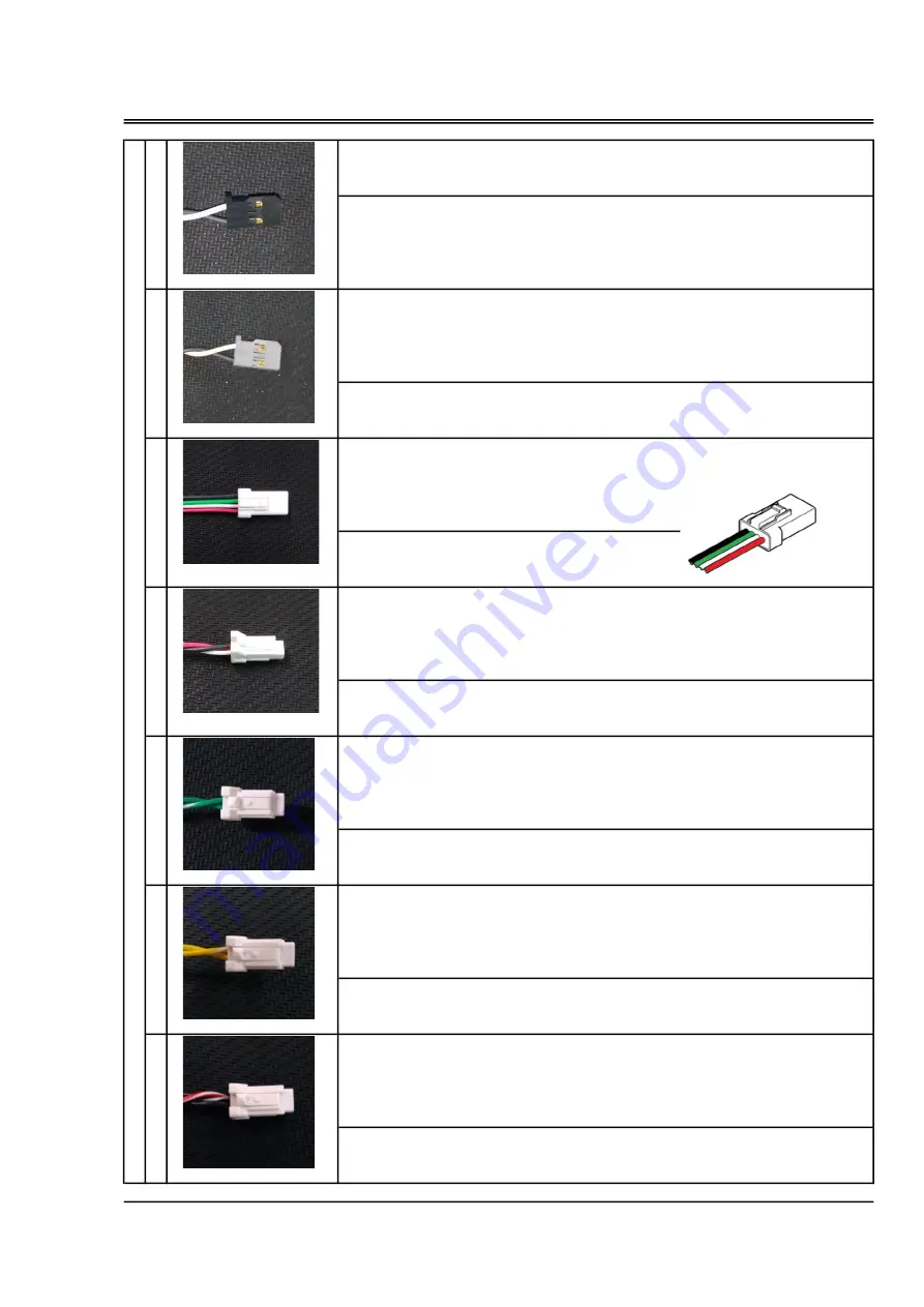
PWM signal
[W
:
Signal
/
B
:
GND] VIH=2.6V
,
VIL=0.4V
,
MAX5.5V
PWM signal
1520μs (neutral) ±420μs
PWM +
→
increase fuel supply The range of increase and decrease is ±30%.
[W
:
Signal
/
B
:
GND] VIH=2.6V
,
VIL=0.4V
,
MAX5.5V
・
the connector for serial communication
UART(TTL logic level is 3.3V.)
[R
:
DC+5V
/
W
:
TX
/
G
:
RX
/
B
:
GND]
Pressure sensor
[R
:
DC+5V
/
W
:
Signal
/
B
:
GND]
PT100 Platinum resistance thermometer
[G
:
No polarity
/
G-W
:
No polarity]
PT100 Platinum resistance thermometer
[Y
:
No polarity
/
Y-W
:
No polarity]
Negative pressure sensor
[R-W
:
DC+5V
/
B
:
Signal
/
B-W
:
GND]
Engine control unit (ECU)
[A
]
A-
1
・
To be connected to a receiver or throttle signal cable from flight controller.
Specification
Set the travel width so that the PWM signal width is 1100 μs or less on the throttle
closed side and the PWM signal width is 1900 μs or more on the throttle opening
side.
Throttle signal input
A-
1
・
In case manual adjustment of fuel injection is necessary, connect to a receiver or
fuel injection signal cable from flight controller.
・
ECU controls quantity of fuel injection normally, so correction signal from the
outside is not necessary. Leave it unconnected or connect 1520μs (neutral) PWM
signal.When pulling out during operation, it holds the state just before.
Specification
Fuel trim signal input
A-
2
・
To be used to monitor parameters or to connect to a computer for initial setting.
Serial communication
A-
3
・
To be connected to Fuel pressure sonsor via Pump connection cord.
Specification
Specification
Fuel pressure sensor
A-
4
・
To be connected to the temperature sensor of the intake port of the throttle valve.
Specification
Intake air temperature sensor
A-
4
・
To be connected to the temperature sensor of the cylinder head.
Specification
Cylinder head temperature sensor
Specification
Manifold air pressure sensor
17
A-
4
・
To be connected to Manifold pressure sensor.
JST
04R-JWPF-VSLE-S
Summary of Contents for GF40U-FI
Page 7: ...6 Accessories CAN communication code the connector for CAN communication...
Page 31: ...PM 02 FUEL PUMP UNIT SP 01 FUEL PRESSURE SENSOR UNIT Engine parts list P1 30 S1 S4...
Page 33: ...VALVE ADJUSTING TOOL KIT GF 32 Engine parts list F10...
Page 34: ...Demantions 33 Unit mm Unit mm...
Page 35: ...Demantions 34 Unit mm...
Page 36: ...MEMO 35...


