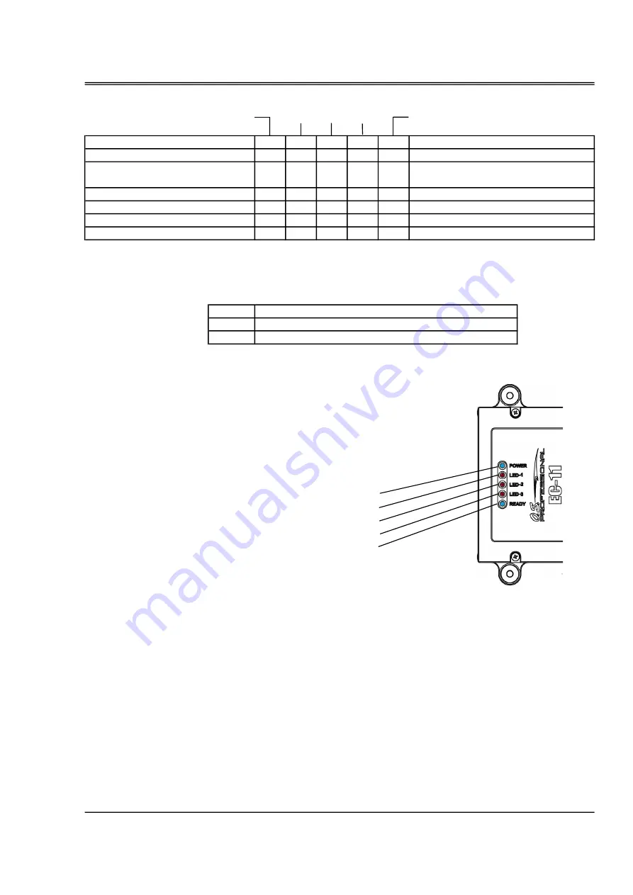
Power LED
Operation status LED
Crankshaft rotation sensor signal input
Injector drive signal output
Igniter started signal output
[Blinking
:
Ready
/
On
:
Working
/
Off
:
Stopped]
Note 1. since the LED1, LED2 and LED3 are the monitor lamp of each signal, so they flashes at high speed
during engine operation.
LED1
LED2
LED3
(note 1.)
at the same time, a buzzer sounds
at the same time, a buzzer sounds
at the same time, a buzzer sounds
at the same time, a buzzer sounds
at the same time, a buzzer sounds
Blink
System error 2
On
Off Blink Blink Off
System error 1
On Blink Blink Blink
Off
The set parameters are damaged
On
Off
Off Blink Off
engine stop
On
Off
Off
On
Blink Off
Off
Off
engine operation
On Blink Blink
21
Operation status LED
Power LED [On
:
Power ON
/
Off
:
Power OFF]
LED 1
LED 2
LED 3
・
the followings are display LED message's meaning.
LED 1 LED2
Operation
LED3
engine start mode
On
Off
Off
Off Blink
Blink On
fuel pressure abnormal
(pressure low)
On
Summary of Contents for GF40U-FI
Page 7: ...6 Accessories CAN communication code the connector for CAN communication...
Page 31: ...PM 02 FUEL PUMP UNIT SP 01 FUEL PRESSURE SENSOR UNIT Engine parts list P1 30 S1 S4...
Page 33: ...VALVE ADJUSTING TOOL KIT GF 32 Engine parts list F10...
Page 34: ...Demantions 33 Unit mm Unit mm...
Page 35: ...Demantions 34 Unit mm...
Page 36: ...MEMO 35...


