background image

15 

e500 User Manual


(15PL1011 - Rev.7  6_6_2017)    English version  

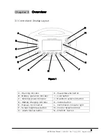
Chapter 4  Preparation for Use 


4.1 Setup 


4.1.1 Connecting electrical power supply 


The e500 is designed to operate using one of the following power options: 


Internal rechargeable battery pack 


AC to DC external power supply. 


Caution 


A fully charged battery must be always installed for safety reasons, even 
when operating from an external power supply so that continuous 
ventilation is not interrupted in absence of external power. 


The use of batteries other than those specified may cause the ventilator 
to fail and/or endanger the patient and operator.         


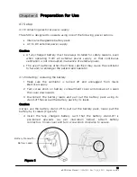
4.1.2 Installing / replacing the battery   


1


Make sure the ventilator is turned off and unplugged from mains 
electrical supply. 


2


Turn screw knob on battery compartment cover anticlockwise to open 
the cover downwards.  


3


Disconnect the battery leads and pull out the battery pack using its 
stand-off. Never pull the battery pack by its leads. 


Caution         


Always use the battery stand off to pull out the battery pack, never pull the 
battery by its leads (Figure 5).  
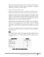
 

4


Insert the fully charged battery such that the battery stand-off is 
positioned upwards (as per illustration below), attach battery 
connectors. Close cover and turn screw knob clockwise to secure.  


Battery Stand off 

Battery Leads 

Figure 5 

Summary of Contents for e500

Page 1: ...e500 User Manual 15PL1011 Rev 7 6_6_2017 English version e500 Automatic Transport Ventilator User Manual ...

Page 2: ...it 10 3 5 Display 11 3 5 1 Screen Layout 11 3 5 2 Live Monitoring Parameters 13 3 6 Symbols Notations 14 Chapter 4 Preparation For Use 5 4 1 Set up 15 4 1 1 Connecting electrical power supply 15 4 1 2 Installing replacing the battery 15 4 1 3 Connecting the gas supply 16 4 1 4 Connecting patient circuit 17 4 1 5 Turning Ventilator ON 17 4 2 Pre use check 18 Chapter 5 Operating Instructions 20 5 1 ...

Page 3: ...aning Disinfection 37 8 2 Charging the Battery 37 8 3 Ambient Air entrainment Filter 38 8 4 Servicing 38 Chapter 9 Technical Data 40 9 1 Specifications 40 9 2 Circuit Description 42 9 3 Battery and Power Supply 43 9 4 Battery Operating time 44 9 5 Electromagnetic Compatibility 45 9 6 Oxygen consumption 47 9 7 Oxygen Concentration delivered against different back pressures 47 Chapter 10 Trouble Sho...

Page 4: ...onfined space will elevate oxygen levels The ventilation setting will be interrupted during battery replacement while the device is in operational mode and the external power supply is not connected Only use O Two specified hoses patient circuits and external power supplies to avoid affecting the output performance of the ventilator Antistatic or conductive hoses or tubing are not used in the Vent...

Page 5: ...ange specified in this manual may result in reduction and or failure in the ventilator s performance In extreme temperature conditions the effect is not noticeable in terms of delivered ventilations but may cause excessive wear in ventilator or components over time Extreme low temperature reduces operation time of the battery Refer to 9 4 battery operating Time Operation of this ventilator outside...

Page 6: ...tor must only be serviced by the manufacturer or its authorized service centers Device single use patient circuits and battery packs should be safely discarded in accordance with local state and institutional laws and procedures Spare O Two patient circuits are recommended at all times The design of this Ventilator does not incorporate a negative pressure phase during either automatic or manual ve...

Page 7: ...emergency and transport ventilator designed for use in the pre hospital intra hospital inter hospital and transport settings It is intended for use with Adult child infant patients with a tidal volume from 100 ml upwards who are in respiratory and or cardiac arrest or respiratory distress and who require the ventilatory support ...

Page 8: ... Resume button B Battery operation indicator I Lock button C External power indicator J Waveform selection button D Battery charging indicator K Cancel button E Manual Hold button L Confirmation indicator light F Screen brightness button M Control Selection Knob G Alarm Silence button N ON OFF button M L H I J K G F E D C B A N Figure 1 ...

Page 9: ...n is selected from the dial If the button is pressed and released for less than a second the ventilator will remain OFF To turn off the ventilator Press and hold the ON OFF button for 4 seconds the green power LED will start flashing at a high frequency After 4 seconds the ventilator will turn off and all ventilation will stop If the button is pressed and held for less than 4 seconds the ventilato...

Page 10: ...t can also be selected when there is no alarm in order to silence potential alarms This function is activated or deactivated by pressing the Alarm Silence button once When selected Alarm Silence symbol will be displayed on the screen 3 2 5 Waveform Pressing Waveform selection button J in figure 1 will switch between the pressure and volume ventilation waveforms displayed on the screen 3 2 6 Screen...

Page 11: ... press the Cancel button K to quit this selection before 10 seconds 3 Once activated a flashing yellow pause symbol will be displayed on the screen and ventilator will stop ventilating Note a During Pause there will be an audible alarm associated with the flashing yellow Warning indicator A in Figure 1 every 15 seconds Users can press Alarm Silence button to disable the audible alarm for 2 minutes...

Page 12: ... I time setting is achieved After I time if the button still pressed the ventilator will switch to inspiratory hold function in which the ventilator will cut the flow but will keep the exhalation port closed in order to block exhaled gas from going to ambient resulting in the maintenance of lung pressure The maximum inspiratory hold time is 6 seconds After that time the ventilator will switch to e...

Page 13: ...Q P O T O DC Input connector P Air Intake filter Q Sensor connector 1 R Sensor connector 2 S 22mm gas output connector T Gas supply input Figure 2 X Y Z λ U Breathing control hose V 2 pressure sensing hoses W one way intake valve X Exhalation port Y breathing valve Z Flow sensor adapter λ Elbow U V W Figure 3 ...

Page 14: ...on parameters Vte Mve Pawpeak PawAV Rate Section 3 Ventilation Modes SIMV CPAP CPR Section 4 Alarms Warnings Section 5 Ventilation waveforms Section 6 Set up parameters Section 7 Confirmation request Patient effort Invalid or Conflict setting Note By changing the ventilation mode section 6 of the display will change accordingly to reflect the default or set up parameters for each mode The followin...

Page 15: ...12 e500 User Manual 15PL1011 Rev 7 6_6_2017 English version CPAP screen layout Masked CPR screen layout Intubated CPR screen layout ...

Page 16: ... will be followed Rate BPM Rate BPM is the rate at which breaths are delivered in one minute It is the monitored breath rate calculated by measuring the time interval Tb in seconds between 2 breaths Rate BPM 60 Tb The number is updated after each breath This number will be displayed for both mandatory and spontaneous breathing phases Vte ml Tidal volume is the volume exhaled from the patient in ma...

Page 17: ...ote Offers useful tips to assist in the proper use of the equipment Confirmation Symbol Invalid Setting Symbol Conflict Setting Symbol Keep away from opened flames No smoking around ventilator IPX4 Ingress protection rating Splash proof Do not immerse Class II equipment Protection against electric doesn t rely on Basic Insulation only additional safety precautions such as Double or Reinforced insu...

Page 18: ...he ventilator to fail and or endanger the patient and operator 4 1 2 Installing replacing the battery 1 Make sure the ventilator is turned off and unplugged from mains electrical supply 2 Turn screw knob on battery compartment cover anticlockwise to open the cover downwards 3 Disconnect the battery leads and pull out the battery pack using its stand off Never pull the battery pack by its leads Cau...

Page 19: ...cylinder o Secure oxygen cylinders so they do not fall over o Keep away from excessive heat to avoid the risk of explosion o Do not grease or lubricate oxygen fittings cylinder valves and pressure reducers and do not handle with greasy hands to avoid the risk of fire o Only open or close cylinder valves by hand or with the correct cylinder wrench Open the valve slowly and fully Do not use any othe...

Page 20: ...4 1 5 and Start up Selection dial Shown in Figure 6 is displayed 4 1 5 Turning Ventilator ON To turn on the ventilator Press the ON OFF button N in Figure 1 for one second During that second the associated green LED will start blinking at a high frequency After 1 second the ventilator will turn on but with no ventilation at this point If the button is pressed and released for less than a second th...

Page 21: ...minimum pressure of 45 PSI 3 Bar and a maximum 87 PSI 6 Bar output pressure a Connect Input hose to input connector T and the other side of input hose to pressure regulator outlet b Connect power supply to DC input socket c Connect the 2 sensor hoses of patient circuit to sensor connectors 1 Q and 2 R and connect the corrugated hose of patient circuit to output connector S Refer to Figure 2 d Once...

Page 22: ...g disconnect power supply the back up system should switch immediately to internal battery power LED indicators should also switch to internal battery 3 Check battery level Do not run the ventilator if battery level is low install a fully charged battery 4 During ventilator cycling observe pressure wave and live ventilation parameters on the screen 5 Disconnect the test lung and check for BCI brea...

Page 23: ... dial Figure 6 is displayed b Start default ventilation Once the ventilator is turned on a selection dial with 12 Vt BPM pre set values Shown in Figure 6 will be displayed on the screen This eliminates the need for a potentially long set up before starting ventilation Note Start up selection dial is used during start up only and are not active during ventilation Healthcare providers navigate among...

Page 24: ...nfirmed the selected area will be highlighted with solid contrast background Figure 9 Navigate among the available settings by rotating the Control Selection Knob M Press the Control Selection Knob M to choose the desired setting The chosen setting will turn yellow with the flashing confirmation symbol and the Confirmation indicator L to guide users to activate the setup by pressing the Control Se...

Page 25: ...L1011 Rev 7 6_6_2017 English version Figure 7 SIMV mode screen w default parameters Child setting Figure 8 Figure 9 Showing frame around Parameter during selection Showing selected Parameter with solid contrasting background ...

Page 26: ...tube or non invasively mask In all modes should the patient demand more flow than set by Health care provider he she can inhale the required volume from ambient Each ventilation mode has a default setting based on the initial patient size setting selection on startup which will be initiated on selection of that specific ventilation mode if no changes to the settings are made Note When switching be...

Page 27: ... mandatory breath before the normal start of inhalation phase beginning of Ti If no effort was detected during the trigger period the ventilator will initiate mandatory ventilation at the end of trigger window Should the patient demand more flow than set by user he she can withdraw the excess from ambient Table 2 Default Ventilation Setting SIMV Parameter Range Default Tidal Volume Rate 100 20 150...

Page 28: ...25 e500 User Manual 15PL1011 Rev 7 6_6_2017 English version Figure 10 SIMV waveform ...

Page 29: ...V when the ventilator does not trigger patient s spontaneous breathing for a period of time T APNEA set by the user The parameters of back up SIMV ventilation are settable by user The trigger changes from pressure trigger P to 3 L min default flow trigger when the ventilator switches to APNEA back up Table 3 Default Ventilation Setting CPAP Parameter Range Default CPAP cm H2O 4 5 6 7 8 9 10 12 15 ...

Page 30: ...27 e500 User Manual 15PL1011 Rev 7 6_6_2017 English version Figure 11 CPAP ventilation waveform ...

Page 31: ... compressions and ventilations is 30 2 Figure 12a The CPR mode for intubated patients consists of continuous compressions indicated by an audible prompt and visual animation at a rate of 100 compressions per minute plus automatically delivered breath every 6 seconds Figure 12b The ventilation in CPR mode is flow controlled ventilation The tidal volume is user selectable The O2 is fixed at 100 oxyg...

Page 32: ...29 e500 User Manual 15PL1011 Rev 7 6_6_2017 English version CPR for masked patients On screen chest compressing animation On screen ventilation animation Figure 12 a CPR waveform for masked patient ...

Page 33: ...30 e500 User Manual 15PL1011 Rev 7 6_6_2017 English version CPR for intubated patients On screen intubated CPR animation Figure 12 b CPR waveform for intubated patient ...

Page 34: ...31 e500 User Manual 15PL1011 Rev 7 6_6_2017 English version 5 3 Turning the Ventilator Off Press and hold the ON OFF button for 4 seconds the Ventilator will turn OFF ...

Page 35: ...upply to the ventilator b Disconnect gas supply hose c Disconnect patient circuit from the output connector d Unplug the power cable from mains if no charging is required e Clean and disinfect according to section 8 1 in this manual 6 2 Storage Store ventilator within the following environmental range 40o C to 60o C Rh 15 to 95 ...

Page 36: ...tinue to flash until the cause of the problem is resolved During alarm silence should a new alarm develop the Alarm Silence function will continue and only the new alarm will be shown flashing on the screen Alarms will be visible in section 4 or section 7 of the display Figure 4 There could be multiple alarm warning symbols visible on the screen indicating multiple failures occurring at the same t...

Page 37: ...ng symbol Red Two bursts with five pulses Low Oxygen 40 PSI Medium Flashing symbol Yellow One burst with three pulses High input pressure 90 PSI High Flashing symbol Red Two bursts with five pulses APNEA High Flashing symbol Red Two bursts with five pulses Empty Battery High Flashing symbol Red Two bursts with five pulses Low Battery Low Flashing symbol N A N A Pause N A Flashing symbol Yellow eve...

Page 38: ...le 6 2 Battery charging status 1 Full Capacity No Alarm 2 95 of full capacity No Alarm 3 90 of full capacity No Alarm 4 80 of full capacity No Alarm 5 65 of full capacity No Alarm Warning At approximately 2 of full battery capacity the ventilator will not start when it is turned off or will shut down when it is turned on Note Battery capacity levels are detected from measured voltages and the capa...

Page 39: ... depends on the severity of the failure Green color LED Continuous when unit is connected to AC power source during both ON and OFF phases Orange color LED Continuous when unit is charging and off when battery is fully charged during both ON and OFF phases During OFF phase this light will start flashing when battery capacity drops to around 90 Green color LED Continuous when unit is operated using...

Page 40: ...ent circuit Using a wet or damp filter may result in inaccurate parameters and potentially damage the ventilator Warning Risk of Explosion Cleaning agents containing alcohol or grease become flammable when combined with compressed oxygen and can cause explosions 8 2 Charging the battery 1 Connect one end of the external power supply charger to its supply 100 to 240 Volts or on board vehicle socket...

Page 41: ... Always keep the ambient air entrainment port clear of obstructions Always replace the filter after use Warning Avoid particulate and or gaseous pollutants in the ambient air The entrainment of pollutants into the ventilator may cause the ventilator to malfunction or cause danger to the patient 8 4 Preventive Maintenance and Servicing It is recommended that routine preventive maintenance PM and se...

Page 42: ...gh use applications Any malfunction unit should be returned to the manufacturer or an authorized service center since this product is not designed for field disassembly or service Unauthorized repairs will nullify the product warranty Level II service The device shall be returned to the manufacturer or a service center authorized by the manufacturer for bi annual Level II service every 2 years Man...

Page 43: ...Maximum Inspiratory hold time 6 sec I E Ratio 1 2 20 PEEP cm H2O 0 4 5 6 7 8 9 10 12 15 18 20 10 or 2 cmH2O CPAP cm H2O 4 5 6 7 8 9 10 12 15 18 20 10 or 2 cmH2O FiO2 60 or 100 15 Pmax cmH2O 10 15 20 25 30 35 40 45 50 55 60 80 10 or 2 cmH2O Pmin cmH2O 0 2 3 4 5 6 7 8 10 12 15 20 10 or 2 cmH2O Trigger sensitivity 3 L min 10 or 2 cmH2O below baseline in CPAP mode only APNEA back up time sec 10 60 0 5...

Page 44: ...ml without mask approx 800 ml with mask Dead space of patient valve with elbow Approx 35 ml Compliance disposable hose system 16 6 ml kPa Resistance of Patient Hose system Inhalation and Exhalation Less than 6 cmH2O at 60 l min Less than 6 cmH2O at 30 l min Environment condition Ventilator Operating 18o C to 50o C Rh 15 to 95 Storage 40o C to 60o C Rh 15 to 95 Battery Pack Charge 0o C to 40o C Dis...

Page 45: ...tilation The output of this valve is connected to a selector switch which is used to direct the flow path either directly to the ventilator output if 100 oxygen ventilation is required or through a Venturi system used to entrain air to provide an oxygen concentration of 60 Patient Optional HME Filter Sensor Adapter Ventilation valve Ventilator Patient circuit Venturi Intake Filter Ambient Flow con...

Page 46: ...behaviour of the ventilator will not be affected while the battery is charging AC DC Power Supply Model PMP90 13 2 01CV0105 Input Voltage 100 240 VAC Input Current 1 06 0 45 A Input Frequency 47 63 Hz Output Voltage 19 VDC Output Current 4 74 A Maximum DC Output Plug 2 5 x 5 5 x 11 mm DC Output Cable Length 6 AC Power Cord Length 6 Weight 642 g EMC performance Meet requirements of IEC60601 1 2 Saf...

Page 47: ...1011 Rev 7 6_6_2017 English version 9 4 Battery Operating Time Battery operation time ranges from 24 hours in Normal operation and temperature conditions to 15 hours in extreme operation and temperature Battery Discharge time ...

Page 48: ...ic establishments and those directly connected to the public low voltage power supply network that supply buildings used for domestic purposes Harmonic emissions IEC61000 3 2 Class A Voltage fluctuations flicker emissions IEC61000 3 3 complies Electromagnetic Immunity Immunity test IEC60601 required test level Actual compliance level Electrostatic discharge ESD IEC61000 4 2 6 kV contact 8 kV air 8...

Page 49: ...can help prevent electromagnetic interference by maintaining a minimum distance between portable and mobile RF communications equipment transmitters and the O Two e500 as recommended below according to the maximum output power of the communications equipment Rated maximum output power of transmitter W Separation distance m 150kHz to 800 MHz outside ISM bands d 3 5 3 P 150kHz to 800 MHz in ISM band...

Page 50: ...85 minutes without PEEP 0 2 min L and is 39 minutes with maximum PEEP 0 089 min L Duration of consumption of a cylinder in minutes is calculated approximately by dividing the liter content by the minute volume with or without PEEP 9 7 Oxygen Concentration delivered against different back pressures 0 10 20 30 40 50 60 70 80 90 100 0 20 40 60 80 100 120 Flow Rate L min O2 Concentration 0 cmH2O 60 cm...

Page 51: ...patient ventilation circuit check tube position adjust Pmax alarm value Apnea spontaneous breathing failed or disconnection faulty sensor Switch to Assist Control ventilation ensure connections tight Replace patient circuit No Oxygen 20 PSI Change Oxygen cylinder Low Oxygen 40 21 PSI Change Oxygen cylinder Leakage measured expiratory volume is 40 lower than set Check leakage in breathing system In...

Page 52: ...tio of inspiration time to expiration time LED Light Emitting Diode Mve Exhaled Minute Volume Mv Minute volume O2 Percentage of Oxygen inspired Paw AV Average airway pressure Paw peak Peak airway pressure PEEP Positive End Expiratory Pressure Pmax Maximum airway pressure Pmin Minimum airway pressure SIMV Synchronized Intermittent Mandatory Ventilation T APNEA Apnea Alarm time Te Expiratory time TF...

Page 53: ...ower supply Cord Canada and the US 01CV0106 5 Battery Pack 01CV9100 6 e Ventilator External Power Supply 01CV0105 7 SMART MOUNT Mounting Bracket for Road ambulance 01EV7035 8 FIXED MOUNT Mounting Bracket for mobile setting 01EV7036 9 1L Test lung 01TA8152 10 Bacterial and Viral Filter case of 40 Bacterial and Viral Filter unit Dead space and Resistance 30 Lpm of Viral and Bacterial filter 26 ml 0 ...

Page 54: ...rs deemed to be out of specification must be returned to O Two Medical Technologies Inc or one of its approved Service Centers for service and or repair We recommend that a service contract be obtained with O Two Medical Technologies Inc or one of its approved Service Centers and that all repairs also be carried out by them Only authentic O Two Medical Technologies Inc spare parts may be used for ...

Page 55: ...e500 User Manual 15PL1011 Rev 7 6_6_2017 English version ...

Page 56: ... SN ____________ O Two Medical Technologies Inc 45A Armthorpe Road Brampton Ontario Canada L6T 5M4 Office 1 905 792 OTWO 6896 N A Toll Free 1 800 387 3405 Fax 1 905 799 1339 Email resuscitation otwo com Web otwo com Marcel Houben Rue Vinave 32 4030 LIEGE Belgique ...

Reviews: