background image

resistance which reduces any unwanted voltage drops as return currents travel through the 
wiring.

This can be done in a variety of ways but one useful and simple method involves having a 
4mm banana socket mounted near each power supply. The banana socket is then connected to
0V, using either the 0VA or 0VB screw terminal on the PSU2 board. Use at least 24/0.2 wire 
to make this connection.

If both the power supplies have a banana socket then it is a simple matter of patching the two 
modular cases together with a banana patch lead. The great thing about bananas is that they 
are stackable so it's easy even if you have more than two cases to connect up.

I recommend that you use thick multistrand cable to make your grounding leads and that you 
use good quality 4mm banana sockets and plugs like the type sold for speaker connections and
not those used for cheap test equipment.

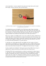
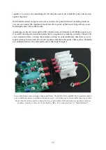
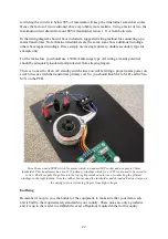
A single M4 crimped ring terminal secured to a panel bonding point. A solder tag with a 4mm hole could

also be used but for thicker wires, like this 24/0.2 wire, crimping offers better performance and is simpler.

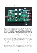
To reduce electrical noise it is wise to ground the panel on which the power supply is 
mounted. To make a 0V bonding point is straightforward. Simply drill a 4mm hole in your 
panel. Scrape back around the hole any finish on the inside surface, such as paint or anodising,
to reveal the shiny metal underneath. Fit an M4 screw from the front and pop on a toothed 
shakeproof washer and flat washer on the rear. Fit your ring terminal (or terminals) onto the 
screw, place another flat washer and shakeproof washer on top of that. Secure tightly with an 
M4 nut. This should ensure that the panel is robustly connected to 0V.

18

Summary of Contents for PSU2

Page 1: ...Oakley Sound Systems PSU2 PCB Issue 1 Project Builder s Guide V1 3 Tony Allgood Oakley Sound Systems CARLISLE United Kingdom 1...

Page 2: ...ment do not worry in this manual I will try to make it clearer so that you make the right decision about what power source you will need It is designed to be mounted onto a metal panel which is used a...

Page 3: ...direct connection to the mains or other high voltage sources further to what is provided in this document Please do not ask me for any additional information pertaining to direct mains connections or...

Page 4: ...tion And the large surface area also allows the power supply s regulators to dissipate heat safely The voltage output of the power supply module is a split rail or bipolar 15V supply This means it gen...

Page 5: ...f standard AC output power supplies are single phase You can tell because they only have a cable with two wires inside which terminates in a two pole connector A single phase AC output supply will all...

Page 6: ...supported normally a red one which lights when any AC power is applied to the unit This would normally be mounted on the outside of the unit alongside the AC power switch and as such the PSU2 makes sp...

Page 7: ...o AC outputs with a centre tap or mid point reference voltage So unlike the single phase AC adapter output with two leads this one has three This means you need to use the Oakley PSU in full wave rect...

Page 8: ...0 This is essentially a bigger version of the PA 20 as detailed above which supplies 18V 0 18V at 1 4A maximum Once rectified smoothed and regulated it can supply up to 0 78A continuously You should a...

Page 9: ...F To prevent loss of the small as the decimal point a convention of inserting the unit in its place is used eg 4R7 is a 4 7 ohm 4K7 is a 4700 ohm resistor 4n7 is a 4 7 nF capacitor Resistors 1 0 25W m...

Page 10: ...D11 1N5819 Schottky diode D3 D10 1N5401 rectifier diode D1 D2 D7 D8 For 1N4004 you can use any other 1N400X part such as 1N4001 1N4002 etc D2 and D8 do not need to be fitted if you are using a single...

Page 11: ...nstallation not requiring a standby switch then you do not need to fit the screw terminal SWITCH F2 and its associating fuse does not need to be fitted if you are using a single phase wallwart or line...

Page 12: ...over the washer and tighten Check that the four holes in the PCB line up with the threaded tops of the hex spacers by temporarily fitting the PCB onto the spacers Loosen and re align any spacer if it...

Page 13: ...ents the mounting screw from touching the regulator s metal tab To fit the device to the panel first place the mounting bush into the hole of the power device with the flange of the bush lying on the...

Page 14: ...s working correctly Check with your continuity tester or using the resistance setting on your multimeter that there is a very high resistance between the tab of each regulator and the metal panel That...

Page 15: ...ched on You can replace the switch with a simple wire link but I do recommend that a switch be fitted so the socket doesn t have to take the full surge current when you insert it with the wallwart pow...

Page 16: ...d S1S together when switched on You can replace the switch with two wire links but I do recommend that a switch be fitted so the socket doesn t have to take the full surge current when you insert it i...

Page 17: ...ore complex system will have perhaps more than one modular more than one mixing desk and perhaps a heap of other outboard equipment This is when it makes sense to look at grounding your modular cases...

Page 18: ...ood quality 4mm banana sockets and plugs like the type sold for speaker connections and not those used for cheap test equipment A single M4 crimped ring terminal secured to a panel bonding point A sol...

Page 19: ...assis ground dirty ground signal ground and clean ground They d all be connected to 0V somewhere in the system but the term ground was in common usage Ground when used in this way is then a local comm...

Page 20: ...een purely luck that has saved me in several of those cases So I will say again do not attempt to build a mains transformer into your modular case or any other project without realising that to do so...

Page 21: ...t power supplies as the AC output of the transformer has to be rectified smoothed and then regulated Therefore the current drawn from a transformer secondary when connected to a standard linear power...

Page 22: ...it an AC standby switch since you will be fitting a proper mains power on switch in series with the transformer primary coil So you should link S1A to S1R and S2S to S2S on the PCB Here I have used a...

Page 23: ...bonding point using at least 24 0 2 wire or by making a second bonding point on the panel For the latter you have one bonding point solely for the mains earth which can be located near the mains IEC i...

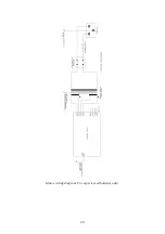
Page 24: ...Mains wiring diagram For experienced builders only 24...

Page 25: ...igital circuitry and LED switching All three would be connected together but only at the power supply However this system would be incompatible with the popular MOTM modular system which only has a fo...

Page 26: ...t one point the PSU MOTM modules can be modified to allow full Oakley compatibility although this should be done as you are building the module Modifying a completed MOTM module is possible but the re...

Page 27: ...voltages Measure the output voltages with respect to ground This means connect your black lead of your voltmeter to the 0VA terminal screw Measure the voltage on the 15V terminal and check that is wit...

Page 28: ...this builder s guide or have a found a mistake in it then please do let me know But please do not contact me directly with questions about sourcing components or general fault finding Honestly I would...

Reviews: