Testing and Calibration
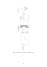
After wiring the unit according to the instructions given in this document you should apply
power to the unit. Check that no device is running hot. Any sign of smoke or strange smells
turn off the power immediately and recheck the all the external wiring first, and then the
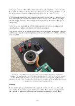
components on the board. Both onboard LEDs should be lit and none of them should be too
bright or too dim. Check too, if you have one, that the standby LED is lit.
Assuming everything is OK so far, it is time to check the output voltages. Measure the output
voltages with respect to ground. This means connect your black lead of your voltmeter to the
0VA terminal screw. Measure the voltage on the +15V terminal and check that is 14
and +16V. Now measure the voltage on -15V and check that this is between -14V and -16V.
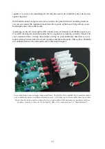
Leave the unit powered up for about ten minutes. Now adjust the voltages with the trimmers
on the board. Adjust ADJ+ to make the +15V terminal equal +15.00V. Adjust ADJ- to make
-15V equal to -15.00V.
The output voltages will vary a little with load. That is, it will change marginally depending on
how many modules you connect up to the power supply board. Feel free to re-adjust the two
trimmers when you add more modules to your project.
27

