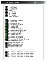
background image

1. Inputs

Input 

Polarity 

Connected to 

Operation when active

I0 

Normally closed 

Kerb lowered

Stops the barrier from raising when kerb interlock ON

I1 

Normally Closed 

Stop circuit 

Barrier stops if door open

I2 

Normally Open 

Raise signal 

Raises Barrier

I3 

Normally Open 

Lower signal 

Lowers barrier

I4 

Normally Open 

Raise limit switch 

Arm has reached its fully open position

I5 

Normally Open 

lower limit switch 

Arm has reached its fully closed position

I6 

Normally Open 

Safety loop Detector/Photocell 

Barrier stops and returns the the raise position until clear.

I7 

Normally Open 

Auto Loop

Raises the barrier from the auto loop
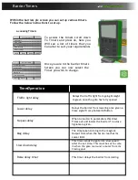
2. Outputs

Output:

Polarity: 

Connected to: 

Operation when active:

Q0 

Normally Open 

Motor controller slow down

Active to slow barrier down

Q1 

Normally Open 

Motor controller open direction 

Active to Raise barrier

Q2 

Normally Open 

Motor controller close direction

Active to lower barrier

Q3 

Normally Open 

Boom Lights

Active to operate boom lights

Q4 

Normally Open 

Traffic light relay

Active when green light in

Q5 

Normally Open 

Maglock or siren

Active to operate maglock or siren (depending on parameters)

Q6 

Normally Open 

Slave raise or Barrier raised

Active to raise the slave barrier or give barrier raised output

Q7 

Normally Closed 

Slave Safety/close or barrier lowered

Active to lower the slave safety or give barrier lowered output
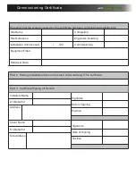
D

3250

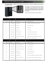
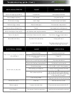
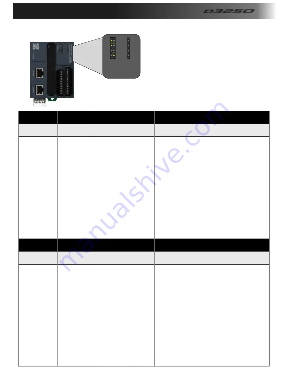
Electrical Troubleshooting guide.

The  table  (bottom)  relates  to  the  diagram  directly  below  to  help  you  trouble  shoot  electrical

component errors

PWR

BAT

RUN

EROR

SD

0
1
2
3
4
5
6
7

0
1
2
3
4
5
6
7

IN 

OUT

M

2

2

1

 T

M

2

2

1

M

1

6

R

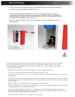
The  image  on  the  left  shows  the  input  and  output
LED  indicators,  use  these  with  the  chart  below
To identify any faults with the barrier. The example
On  the  left  shows  that  the  barrier  is  lowered,  the
Photocells/loop  are  healthy  and  the  stop  circuit  is
Also healthy.

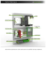
Note, the PLC is located in the barrier cabinet.

Summary of Contents for D3250

Page 1: ...Maximum span 7 0 100 Duty cycle Automatic Barrier d3250 Made in the...

Page 2: ...07 09 7 Commissioning Certificate Page 10 8 Manual release Page 11 9 Terminal connections Page 12 10 Control panel layout Page 13 11 Using the controller Display Page 14 12 Barrier Parameters Page 15...

Page 3: ...ade to be 100 accurate in this manual but we cannot make any guarantees As we constantly innovate our products we may change the quoted spec and any other details that have been documented in this man...

Page 4: ...It covers the main areas that cause the majority of injuries and ill health to workers including Workplace transport Slips trips and Musculoskeletal disorders MSD The movement of goods presents us as...

Page 5: ...installation of a D3250 Automatic barrier for a single entrance Control Dual height Card access entry Loop safety lower with Auto loop exit Shown above is a very basic layout There are many types of...

Page 6: ...General Layout Foundation drawing D3250...

Page 7: ...order as they are referred to throughout this manual note this can change per barrier spec i e manual components are different from automatic Barrier Cabinet c w Pole Arm Adaptor End Rest Pole if ove...

Page 8: ...ater Then after checking the barrier is Still in line and level proceed to drill and bolt in the Rest of the fixing bolts Once all bolts are in make Sure they are tightened down Guide to Physical Inst...

Page 9: ...in shaft that operate the limit Switches These are what you may need to adjust For example if the pole is stopping short of its tip Support in the lower position then you will need to Back the lower s...

Page 10: ...ineers Installing Commissioning Equipment Fitted Handover Date Part 2 Existing Installation Items not covered under warranty This certificate Installers Name On Behalf of Address Signature Date of Sig...

Page 11: ...every 6 months or sooner dependant on use Barrier will not work properly without photo cell function Have a qualified technician installer check the correct setting of the electric clutch If the power...

Page 12: ...rier 17 Connect to terminal 5 in slave barrier 18 Connect to terminal 4 in slave barrier 19 Connect to terminal 3 in slave barrier When used as a Master Barrier below terminals will be situated on the...

Page 13: ...yout 240v Terminals 240v Breaker 24VDC Power supply PLC Inverter Loop Detector Low voltage terminals 24v Fuse 1Amp Programming screen Above shows a typical barrier control panel layout which identifie...

Page 14: ...interface You will see the screen shown in The left diagram which shows Settings you can alter One very Useful feature is the R4 and R3 Key can raise and lower the barrier As shown in the bottom righ...

Page 15: ...network cable this Option turns on the outputs to run an inverter hard Wired OFF Raise Timeclock This turns ON the raise timeclock which will hold the Barrier up at set times of the day See timeclock...

Page 16: ...change D3250 Barrier Timers Lower delay Slow down delay Traffic light delay Lower delay No pass delay Slow down delay Delays the traffic light from going Straight to green once the gate has fully open...

Page 17: ...eriod 1 Select Alarm On Time Off Time 0900 1700 In Range 0 When you select a period time set it will Take you to the on off time for that Period you can now set the times you Need the barrier to stay...

Page 18: ...Open Motor controller close direction Active to lower barrier Q3 Normally Open Boom Lights Active to operate boom lights Q4 Normally Open Traffic light relay Active when green light in Q5 Normally Ope...

Page 19: ...Blank screen on PLC but power to other devices in the control panel On board fuse blown Replace fuse and reset barrier PLC has developed an electrical fault or had a power spike Change PLC Barrier do...

Page 20: ...the photocell optical components and make sure they are free from dirt water rain soil etc Batteries in photo cells may need to be changed every 6 months or sooner dependant on use Barrier will not wo...

Page 21: ...e repair work is carried out on the product This is to achieve two things 1 To keep a history of the product for yourself and your supplier manufacturer 2 To keep an accurate log of any historical or...

Page 22: ...5 Amps Drive Motor 3 Phase motor wormed gearbox Opening Closing time 1 5 7 0 seconds Duty Cycle 100 continuos duty rating Operation Time 8 Seconds per metre Variable Finish Polyester Powder Coated Di...

Reviews: