

/
/
20
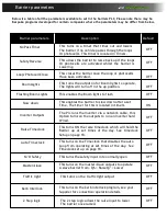
Important Safety Notice
Automatic barriers are designed to Control the flow of vehicular
traffic only. It can be dangerous to allow the passage of
pedestrians and any other self-powered animal or device to
utilise this method of access without appropriate warnings and or
signage.
It may be necessary for the end user of this product to provide
an alternative, safe method of access to cater for the previously
mentioned categories.
The end user should fit all necessary signage and warning
notices to either side of the gate, which should be visible and
clear from all directions of approach.
The product that was shipped to you was designed with a control
program to protect all categories from harm or affect this
however is only a safety precaution and should not be modified
or tampered with by any unauthorised person not sanctioned by
the manufacturer.
Please sign and date below to say that you have read and
understood this notice before ANY installation work:
The “Warnings” leaflet and “Instruction booklet” supplied with this
product should be read carefully as they provide important information
about safety, installation, use and maintenance.
Scrap packing materials (plastic, cardboard, polystyrene etc) according
to the provisions set out by current standards. Keep nylon or polystyrene
bags out of children's reach.
Keep the instructions together with the technical brochure for future
reference.
This product was exclusively designed and manufactured for the use
specified in the present documentation. Any other use not specified in
this documentation could damage the product and be dangerous.
The Company declines all responsibility for any consequences resulting
from improper use of the product, or use which is different from that
expected and specified in the present documentation.
Do not install the product in explosive atmosphere.
The construction components of this product must comply with the
following European Directives: 89/336/CEE, 73/23/EEC, 98/37/EEC
and subsequent amendments. As for all non-EEC countries, the abovementioned
standards as well as the current national standards should
be respected in order to achieve a good safety level.
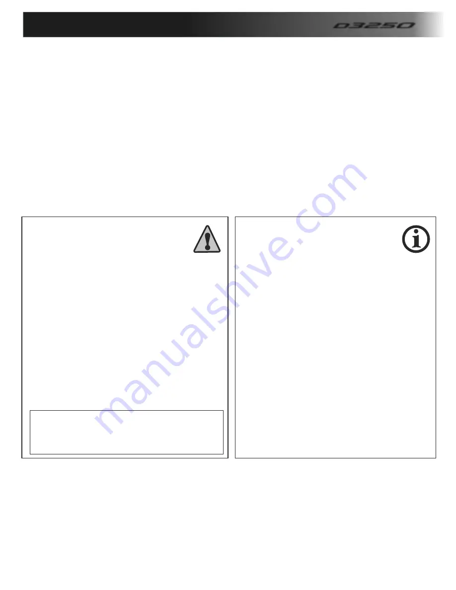
Information on using
this manual
?
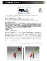
Read all information thoroughly
?
Pay attention to all safety advice
?
Be aware of the symbols (shown above right and
above left) as they have different meanings. One is an
information symbol, the other a warning.
?
There are many artists impressions of the product in
this manual you should refer to the images as a guide
only. Professional CAD drawings should be used as
a reference drawing and nothing else. As before every
effort has been made to be 100% accurate in this
manual but we cannot make any guarantees.
?
As we constantly innovate our products we may
change the quoted spec and any other details that
have been documented in this manual so you should
always refer to the supplier to see if the manual that
was shipped with your product is the latest edition.
?
As with all electrical installations you should use a
qualified electrician and obey all of the latest laws and
regulations.
?
Be sure to fill out and complete ALL paperwork where
instructed as this manual is the equipments log book
and maintenance manual.
The Company declines all responsibility for any consequences resulting
from failure to observe Good Technical Practice when constructing
closing structures (door, gates etc.), as well as from any deformation
which might occur during use.
The installation must comply with the provisions set out by the following
European Directives: 89/336/CEE, 73/23/EEC, 98/37/EEC and
subsequent amendments.
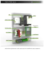
Disconnect the electrical power supply before carrying out any work on
the installation. Also disconnect any buffer batteries, if fitted.
Fit an omnipolar or magnetothermal switch on the mains power supply,
having a contact opening distance equal to or greater than 3mm.
Check that a differential switch with a 0.03A threshold is fitted just before
the power supply mains.
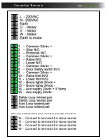
Check that earthing is carried out correctly: connect all metal parts for
closure (doors, gates etc.) and all system components provided with an
earth terminal.
Fit all the safety devices (photocells, electric edges etc.) which are
needed to protect the area from any danger caused by squashing,
conveying and shearing, according to and in compliance with the
applicable directives and technical standards.
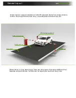
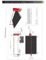
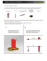
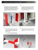
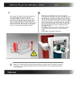
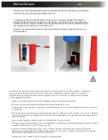
This equipment is part of a large range of traffic flow products. They are designed to be easy to install, as
all settings and internal wiring have been completed in our factory. Any of the instructions in this manual
should only be carried out by a qualified service engineer or a competent person.
The barriers are ready to bolt down, connect to a single phase power supply and have any pre-cut loops
wired into them (Please note that loop detectors are sold separately). The steps must be completed before
the power is turned on to prevent accidents.
The following information is a guide only, and whilst we have made every effort to be accurate and correct
there may be printing errors which we cannot be held responsible for.
With a correct installation you can expect to enjoy many years of reliable service from this product, we do
however recommend that the product has a bi-annual service carried out by a qualified engineer. Please
contact our service department to obtain a quote. As we manufacture the products we are best suited to
care for your equipment.
Introduction and Warnings
D
3250