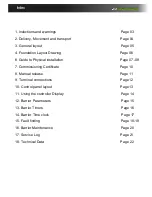
7
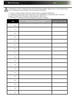
Notes area
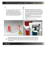
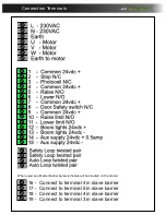
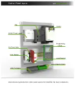
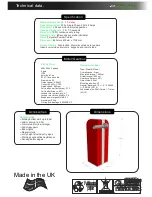
Now connect all Induction loops, Mains power and
Any other accessories you have using the
Connection diagram on page 8. Once you have
Everything connected you can then power up and
test. You must check that all safety accessories
Work correctly first and then move on to testing any
Access control fitted. Below shows a basic keypad
Entry, auto exit and loop lower/safety system.
D
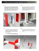
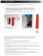
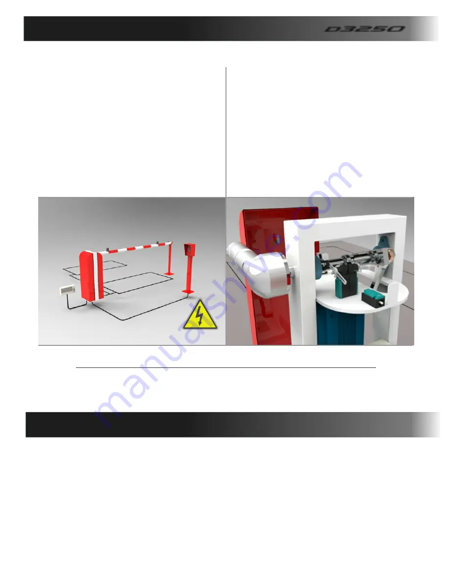
epending on pole length you may now be required
To adjust the limit switches if the pole is not finishing In the
desired position. You will see the two Limit strikers on the
main shaft that operate the limit Switches. These are what
you may need to adjust, For example if the pole is stopping
short of its tip Support in the lower position then you will
need to Back the lower striker off so it hits the switch later
Allowing the pole to travel further. Depending on what
handing the barrier
Is depends on which limit switch does the raise or lower.
You will clearly see which one you need to adjust by
looking
At the position of the barrier to the pole.
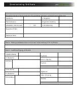
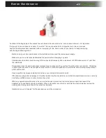
Make sure to check all your connections and the barrier is earthed correctly. Also ensure the barrier
covers are on correctly and the safety switch is operated. Now fill out the commissioning certificate
on the Next page.
9
D
3250
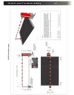
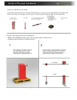
Guide to Physical Installation. (Cont)
8
earth product
Notes area