background image

7

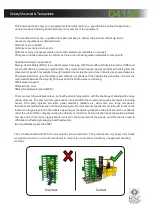
earth product

Notes area

Guide to Physical Installation (Cont)

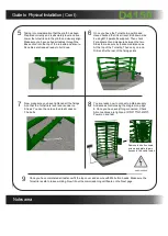
Tak ing into con s ide r ati on th at t h e plinth has been

  6 

Once you have the Turnstile in position and
Have checked that it is all level, Bolt down side
2 using M12 parabolts supplied. Then check
For alignment and measure between the two
Sides to make sure its that same distance as
At the top of the Turnstile, Then carry on and
Drill and fix the rest of the fixing points.

Now make sure you have tightened all the fixings
And that the Turnstile is level and is under no
Stress. You can then place the plastic caps on
The bolts.

You are ready now to connect up Mains supply
And access control using the diagram on page
8. Once you have everything connected, Check
All connections are tight and correct. Then switch
Power on and test.

Once you have completed all tests now fit the top cover and secure with M6 button heads. Make sure the
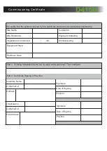
Turnstile is safe to leave working. Now fill out the commissioning certificate on the Next page.

9

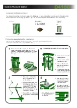
Prepared correctly and is absolutely level and true,
Lower the turnstile onto the plinth and visually align.
Make sure you have pulled all cables through the
Box section into the top of the turnstile and ensure
No cables are trapped ready to bolt down.

Remove the button head
screws and plate to gain
Access to the cable routes.

D4150

Summary of Contents for D4150

Page 1: ...120 Rotor 100 Duty cycle Made in the Full Heig ht Turns tile D4150...

Page 2: ...cumentation Any other use not specified in this documentation could damage the productand be dangerous The Companydeclines all responsibility for any consequences resulting from improper use of the pr...

Page 3: ...l health arising from the movement of goods from supplier through haulier to the recipient and end user including any home deliveries The project will focus upon the delivery and collection of goods a...

Page 4: ...he Turnstile will either be on a Pallet or flat packed If flat packed then follow Step s 2 4 if already assembled carry on to step 5 Note please check for physical damage before You sign Turnstile Box...

Page 5: ...lastic caps on The bolts 8 You are ready now to connect up Mains supply And access control using the diagram on page 8 Once you have everything connected Check All connections are tight and correct Th...

Page 6: ...ineers Installing Commissioning Equipment Fitted Handover Date Part 2 Existing Installation Items not covered under warranty This certificate Installers Name On Behalf of Address Signature Date of Sig...

Page 7: ...mplying with the appropriate legislation Before carrying out any maintenance to the installation Isolate the mains power supply Make sure you have disconnected Isolated the power before attempting any...

Page 8: ...Connection Terminals Layout PLC 24VDC Power supply D4150...

Page 9: ...Connected to Operation when active I1 Normally Open Free wheel Free wheels in both directions I2 Normally Open Entry signal Allows one person through the entry of the turnstile I3 Normally Open Exit s...

Page 10: ...Top Cog Spring assist requires lubrication Lubricate both items Turnstile Rotor is tight Turnstile is out of square level check turnstile frame is all square level Turnstile Rotor is tight Bottom bea...

Page 11: ...e repair work is carried out on the product This is to achieve two things 1 To keep a history of the product for yourself and your supplier manufacturer 2 To keep an accurate log of any historical or...

Page 12: ...pecification Power Requirement Arms and body Duty Cycle Flow Rate Key Points Access Controls 220 v Single Phase 50 Hz 5 Amps Primed Powder Coated finish 100 continuous duty rating 15 to 22 min in a si...

Reviews: