Electrical Troubleshooting Guide
PF4000FH
11
Menu/Ok
SR2 B121BD
1
2
Q1
1
2
Q2
1
2
Q3
1
2
Q4
+
-
I1
I2 I3 I4 IB
ID
IC
IE
24VDC
24VDC
24VDC
Analog or
IB....IE
Inputs I1...I4
Outputs
Q1...Q4 : Relay 8A
1. Inputs
Input
Polarity
Connected to
Operation when active
I1
Normally Closed
Lock
Turnstile stops if door open
I2
Normally Open
Entry Signal
Raises Turnstile
I3
Normally Open
Exit Signal
Lowers Turnstile
I4
Normally Open
Entry Limit
Detects Vehicle on loop then lowers if no detection present
IB
Normally Open
Exit Limit
Detects vehicle on loop/Lowers when not detected
IC
Normally Open
Freewheel
Turnstile opens when vehicle present on loop
ID
Normally Open
Spare Input
Arm has reached fully closed position
IE
Normally Open
Not Used
Spare not used
2. Outputs
Output:
Polarity:
Connected to:
Operation when active:
Q1
Normally Open
Q1(1) = 24v Common
Q1(2) = Entry Solenoid
Active to open Turnstile
Q2
Normally Open
Q2(1) = 24v Common
Q2(2) = Exit Solenoid
Active to close Turnstile
Q3
Normally Open
Spare
Spare Not Used
Q4
Normally Open
Spare
Spare Not Used
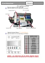
The table (bottom) relates to the diagram directly below to help you trouble shoot electrical component errors
Menu/Ok
SR2 B121BD
1
2
Q1
1
2
Q2
1
2
Q3
1
2
Q4
+
-
I1
I2 I3 I4 IB
ID
IC
IE
24VDC
24VDC
24VDC
Analog or
IB....IE
Inputs I1...I4
Outputs
Q1...Q4 : Relay 8A
1.
2.
1
B
234
CDE
RUN LD
SUN 20 JUL
09:36
1234
1234
BCDE
STOP LD
SUN 20 JUL
09:37
2 4
1 3
Input displays
which change
as inputs used
detailed in the
table below.
Example
showing number
I1 and IB input
selected
Showing program in “run mode”
Showing program in “Stop mode”
Output displays
which change
as Outputs used
detailed in the
table below.
Example
showing number
Q1 and Q3
output selected
Date/Time Display
Date/Time Display
Note:
For custom programs or “bespoke” solutions please contact us. Do not attempt to modify or change the
program without prior consent as this may pose a health & safety risk. Always use a qualified technician to
make any major changes to the generic control program.
!


