Guide to Physical Installation (cont)
PF4000FH
5
Notes area
PF4000FH
9.
5/6.
7/8.
10.
45 mins
5/6.
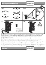
Shown in this illustration is the mounting holes on single turnstile (left) which has 7 mounting points.
Also shown (right) is the double turnstile which has 12 mounting points. Please note that this must be
installed not under duress or strain. You should make sure that the uprights are level you can use a
straight building level for this.
7/8.
This illustration shows the standard access control mounting plate. This basic illustration shows the
fixing point top and bottom. Also it shows the ducting hole where you should pull your access cable
through. This item is standard and if not required should be made clear at the point of order.
9.
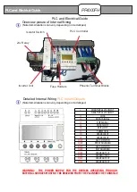
Now connect all power and access control using the wiring diagram on page 8. For any other specific
wiring access control wiring details please contact your supplier.
10.
Just remember to check all connections and the turnstile is earthed. Make sure the lid is closed (this is
for safety reasons as the electrics will be exposed) , and make sure it is safe for the turnstile to operate.
60 5
10
15
20
25
30
35
40
45
50
55
Live
Nuteral
Power Supply
(MCB)
1
2
3
4
5
6
7
8
9
#
*
0
Example showing
different items attached
to turnstile. These are
just a few of many that
can be attached as long
as they are volt free!
earth product
Directional Indicators
Black boxes show fixing points from a “birds eye view”
Fixed rear plate
Security screw
Front mounting
plate
Duct hole
Upright stansion
Security screw


