- GB -
19
Start-up
Attention!
Dangerous electrical voltage.
Possible consequences:
Death or severe injury.
Protective measures:
•
Prior to reaching into the water, switch off the mains voltage to all units used in the water.
•
Switch off the mains voltage prior to carrying out work on the unit.
Note!
If the water flow is suddenly interrupted downstream of the outlet (e.g. with a slide valve), this can lead to a
brief increase of pressure of more than 1 bar (water hammer).
Possible consequences:
The unit may be damaged.
Protective measures:
•
Switching off: First switch off the pump, then close the slide valve. If the unit is operated in a filter system,
first take the filter system out of operation.
•
Switching on: First open the slide valve, then switch on the pump. If the unit is operated in a filter system,
start up the filter system last.
•
Install the slide valve upstream of the inlet.
When using filter starter, medicines or pond water treatments, leave the UVC clarifying unit switched off for at
least 36 hours so as not to impair their efficacy.
Prerequisite
•
Switch the pump on first, then switch on the UVC clarifying unit.
•
Check all connections for leaks.
Switching ON/switching OFF
•
Switching on:
Insert the power plug into the socket.
−
The unit switches on immediately.
•
Switching off:
Disconnect the power plug.
Check the function.
I
•
The function display is lit when the UVC lamp is switched on.
•
An alternating light/dark blue glow in the inspection window indicates that the cleaning rotor is rotating.
Setting the bypass
The flow rate is controlled by the bypass. Depending on the setting, part of the water flows from the inlet directly out via
the opposite outlet. The remaining part of the water is irradiated by the UVC light and flows out via the second outlet.
Maximum cleaning capacity is only achieved with an optimum setting.
4.
0.
How to proceed:
J
•
Set both rotary handles to the delivery rate of the filter pump.
GA_29273_01-14_ Bitron_C_24W-11019 19
13.01.2014 10:37:15
Summary of Contents for Bitron C Series
Page 1: ...29273 12 E Bitron C UVC 29273 GAW Bitron UVC A6_end 09 12 2009 11 09 Uhr Seite 2...
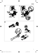
Page 3: ...3 F BTN0035 G BTN0032 GA_29273_01 14_ Bitron_C_24W 1103 3 13 01 2014 10 37 14...
Page 4: ...4 H BTN0031 I BTN0026 J BTN0025 GA_29273_01 14_ Bitron_C_24W 1104 4 13 01 2014 10 37 14...
Page 5: ...5 K L BTN0027 BTN0028 M BTN0034 GA_29273_01 14_ Bitron_C_24W 1105 5 13 01 2014 10 37 15...
Page 6: ...6 N BTN0029 GA_29273_01 14_ Bitron_C_24W 1106 6 13 01 2014 10 37 15...
Page 111: ...RU 111 1 36 I 4 0 J GA_29273_01 14_ Bitron_C_24W 110111 111 13 01 2014 10 37 19...
Page 119: ...CN 119 1 UVC 36 I 4 0 J GA_29273_01 14_ Bitron_C_24W 110119 119 13 01 2014 10 37 19...
Page 126: ...126 BTN0030 GA_29273_01 14_ Bitron_C_24W 110126 126 13 01 2014 10 37 19...
Page 127: ...GA_29273_01 14_ Bitron_C_24W 110127 127 13 01 2014 10 37 19...
Page 128: ...24231 01 14 GA_29273_01 14_ Bitron_C_24W 110128 128 13 01 2014 10 37 19...

