- GB -
21
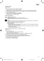
Fitting the unit head
3.
0.
How to proceed:
L
1. Position the O ring in front of the recess at the unit head.
−
Ensure that the O ring is clean; replace if damaged.
2. Carefully push the unit head with cleaning rotor into the casing up to the stop while applying light pressure.
−
Ensure that that the unit head is turned such that the markings on the unit head and casing are aligned.
3. Turn the unit head up to the stop.
−
Ensure that the safety engagement catch engages.
4. Close the locking screw in the safety engagement catch.
−
Rotational direction "Lock closed" symbol.
Cleaning the quartz glass
Attention!
Breakable glass.
Possible consequences:
Injury to your hands caused by cuts.
Protective measures:
Handle the quartz glass and UVC lamp with care.
Note!
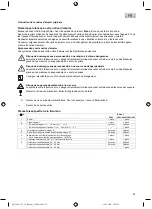
If the water flow is suddenly interrupted downstream of the outlet (e.g. with a slide valve), this can lead to a
brief increase of pressure of more than 1 bar (water hammer).
Possible consequences:
The unit may be damaged.
Protective measures:
•
Switching off: First switch off the pump, then close the slide valve. If the unit is operated in a filter system,
first take the filter system out of operation.
•
Switching on: First open the slide valve, then switch on the pump. If the unit is operated in a filter system,
start up the filter system last.
•
Install the slide valve upstream of the inlet.
Prerequisite: The device head is removed. (
→
Removing the unit head)
5.
0.
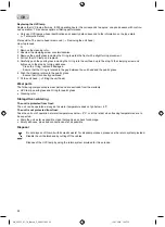
How to proceed:
M
1. Remove the cleaning rotor.
−
Clean the cleaning rotor with a brush under running water.
−
Wipe the quartz glass with a damp cloth.
−
Replace the quartz glass if it is damaged or very scratched. (
→
Replacing the UVC lamp)
2. Clean the inner and outer surfaces of the casing and inspection window.
3. Check the profile wear at both ends and the inner surfaces of the cleaning rotor.
−
If the profile is worn, the cleaning rotor will rotate sluggishly and has to be replaced.
4. Push the cleaning rotor onto the quartz glass.
−
Ensure that it is correctly positioned.
5. Fit the unit head. (
→
Fitting the unit head)
GA_29273_01-14_ Bitron_C_24W-11021 21
13.01.2014 10:37:15
Summary of Contents for Bitron C Series
Page 1: ...29273 12 E Bitron C UVC 29273 GAW Bitron UVC A6_end 09 12 2009 11 09 Uhr Seite 2...
Page 3: ...3 F BTN0035 G BTN0032 GA_29273_01 14_ Bitron_C_24W 1103 3 13 01 2014 10 37 14...
Page 4: ...4 H BTN0031 I BTN0026 J BTN0025 GA_29273_01 14_ Bitron_C_24W 1104 4 13 01 2014 10 37 14...
Page 5: ...5 K L BTN0027 BTN0028 M BTN0034 GA_29273_01 14_ Bitron_C_24W 1105 5 13 01 2014 10 37 15...
Page 6: ...6 N BTN0029 GA_29273_01 14_ Bitron_C_24W 1106 6 13 01 2014 10 37 15...
Page 111: ...RU 111 1 36 I 4 0 J GA_29273_01 14_ Bitron_C_24W 110111 111 13 01 2014 10 37 19...
Page 119: ...CN 119 1 UVC 36 I 4 0 J GA_29273_01 14_ Bitron_C_24W 110119 119 13 01 2014 10 37 19...
Page 126: ...126 BTN0030 GA_29273_01 14_ Bitron_C_24W 110126 126 13 01 2014 10 37 19...
Page 127: ...GA_29273_01 14_ Bitron_C_24W 110127 127 13 01 2014 10 37 19...
Page 128: ...24231 01 14 GA_29273_01 14_ Bitron_C_24W 110128 128 13 01 2014 10 37 19...


