15
- GB -
Safe operation
•
Never operate the unit if either the electrical cables or the housing are defective!
•
Do not carry or pull the unit by its electrical cable.
•
Route cords/hoses/lines in a way that they are protected against damage, and ensure that they do not present a
tripping obstacle.
•
Only open the unit housing or its attendant components, when this is explicitly required in the operating instructions.
•
Only execute work on the unit that is described in this manual. If problems cannot be overcome, please contact an
authorised customer service point or, when in doubt, the manufacturer.
•
Only use original spare parts and accessories for the unit.
•
Never carry out technical modifications to the unit.
•
The power connection cables cannot be replaced. When the cable is damaged, the unit or the component needs to
be disposed of.
•
Only operate the unit if no persons are in the water!
•
The unit, the connections and plugs are not water-proof and must not be routed or installed in water.
•
Keep the socket and power plug dry.
Installation and connection
Prerequisite
•
The unit head is removed. (
→
Removing the unit head)
Set-up the unit
9.
0.
How to proceed:
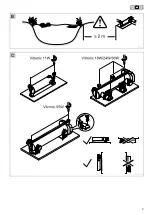
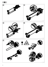
B, C
•
Install the unit at least 2 m from the edge of the pond.
•
Only install the unit in the permitted positions to ensure fault-free operation.
•
Allow sufficient space for carrying out maintenance work.
Connect the unit
Use hoses that are suitable for a pressure of at least 1 bar.
1.
0.
How to proceed:
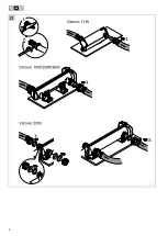
D
1. Shorten the stepped hose adapter to the diameter of the hose used if necessary.
−
This reduces pressure losses.
2. Connect the hose with the stepped hose adapter and secure with a hose clip.
−
In the case of a stepped hose adapter with separate union nut, first push the union nut over the hose.
3. Connect the stepped hose adapter with seal to the casing.
−
Connect the inlet and outlet.
−
Hand tighten the stepped hose adapter.
Connect the unit to the flow-through filter.
Vitronic 18 W / 24 W / 36 W
The unit is suitable for connection to flow-through filters. Both outlet sockets are screwed to the inlet nozzles on the
flow-through filter. Adhere to the instructions for use of the flow-through filter.
4.
0.
How to proceed:
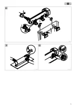
E
1. Unscrew the cover cap.
2. Guide the outlet sockets with flat seal through both holes in the container wall of the flow-through filter.
3. Screw the inlet nozzle with O ring onto the outlet socket and hand tighten. (es gibt aber 2 Auslaufstutzen?)
4. Connect the supply hose to the inlet socket. (
→
Establish connections)
Summary of Contents for Vitronic 55 W
Page 1: ...00000 07 13 Vitronic 11 55W GAW_Vitronic_A5_end_ 25 07 13 13 56 Seite 2...
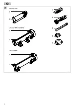
Page 2: ...2 A VTC0001...
Page 3: ...3 B VTC0016 C VTC0006...
Page 4: ...4 D VTC0007...
Page 5: ...5 E VTC0011 F G VTC0009 VTC0010...
Page 6: ...6 H I VTC0002 VTC0003 J K VTC0004 VTC0005 L VTC0008...
Page 52: ...142 VTC0014 VTC0012...
Page 53: ...143 VTC0013...
Page 54: ...22204 09 13...


