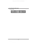
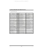
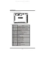
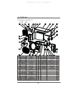
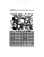
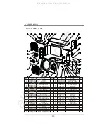
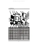
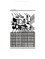
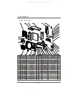
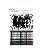
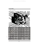


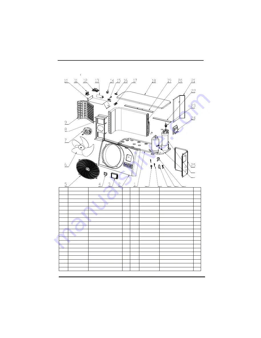
6.2 Explosive view of the unit
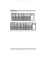
MODEL
h
EH9
6.APPENDIX
30
Code
32012-210267
32012-210266
20000-220068
95005-310152
20000-220188
3500-2701
3404-3301
32012-210229
32012-210274
32012-210228
2000-3619
95005-310145
2000-3505
2000-3501
20000-370003
2000-3909
4000-3901
32012-210270
32012-210225
32012-120030
32012-210227
Part name
Chassis
Front panel
LED water proof box
Cm100 touch LCD
Fan protection net
Axial fan
Axial fan motor
Fan bracket
Rear Grill
HW200 PC1001
Electrical box
Relay
Compressor capacitor
Fan capacitor
Transformer
Two-seat connector
Five-seat connector
Top cover
Top support plate 2
Fin heat exchanger
Middle separation panel
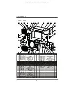
Code
32012-210224
20000-360005
20000-220249
32012-210269
32008-120034
20000-110117
20000-140238
2000-3603
2004-1444
20000-140150
2001-3605
NO.
1
2
3
4
5
6
7
8
9
10
11
12
13
14
15
16
17
18
19
20
21
NO.
22
23
24
25
26
27
28
29
30
31
32
Note
Note
Part name
Top support plate 1
Water flow switch
Handle
Right-side panel
Titanium heat exchanger
Compressor
Electronic expansion valve
Pressure switch
Filter(R410A)
Pin Valve
Pressure switch
26
27
28
29
30
31
32
All manuals and user guides at all-guides.com


