background image

OVERVIEW 


 

These Structural Concepts merchandisers are 

designed to merchandise packaged products at 41 °F 

(5 °C) or less product temperatures. 

 

Cases should be installed and operated according to 

this operating manual’s instructions to ensure proper 

performance. Improper use will void warranty. 


TYPE 1 vs. TYPE 2 CONDITIONS 


This unit is designed for the display of products in ambient 

store conditions where temperatures and humidity are 

maintained within a specific range.   


 

Self-Contained cases are designed for Type 1 

conditions: Ambient conditions at 55% maximum 

humidity and maximum temperatures of 75 °F (24 °C).   

 

Remote cases are designed for Type 2 conditions: 

Ambient conditions at 60% maximum humidity and  

maximum temperatures of 80 °F (27 °C).   

 

If unsure if your case is designed for Type 1 or Type 2 

conditions, see identifier label on your case.  Location 

may vary.


COMPLIANCE 


 

Performance issues when in violation of applicable 

NEC, federal, state and local electrical and plumbing 

codes are not covered by warranty. See below. 


WARNINGS 


 

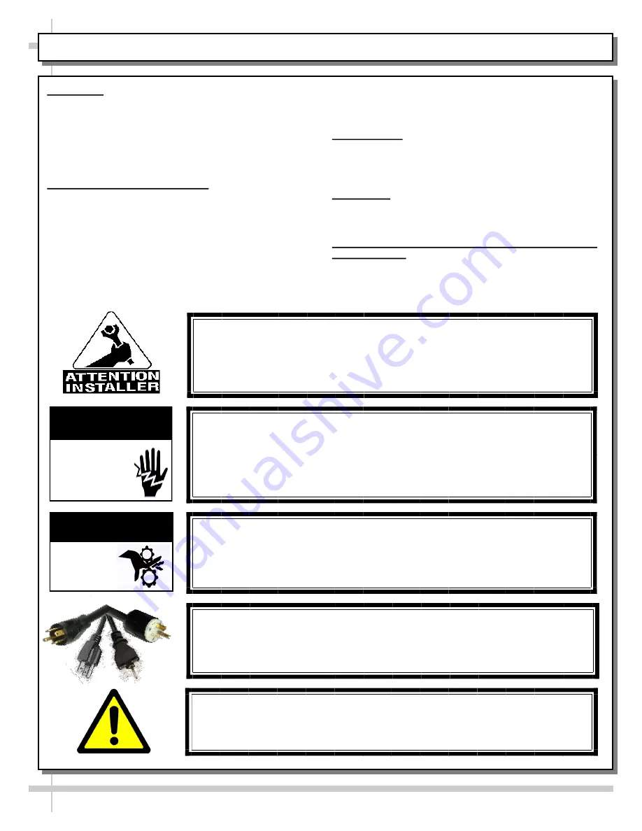
This sheet contains important warnings to prevent 

injury or death. Please read carefully! 


PRECAUTIONS, MAINTENANCE & WIRING DIAGRAM 

INFORMATION 


 

See next page for 

PRECAUTIONS, MAINTENANCE 

and

 WIRING DIAGRAM

 information.


WARNING 


Hazardous moving parts.  Do not operate unit with covers removed.   

Fan blades may be exposed when deck panel is removed.   

Disconnect power before removing deck panel. 

WARNING  


Risk of electric shock. Disconnect power before servicing unit. 

CAUTION!  More than one source of electrical supply is                        

employed with units that have separate circuits.   

Disconnect ALL ELECTRICAL SOURCES before servicing. 


WARNING 

ELECTRICAL 

  HAZARD


WARNING 

KEEP 

HANDS 

COMPLIANCE 


This equipment MUST be installed in compliance with 

all applicable NEC, federal, state and local  

electrical and plumbing codes. 

OVERVIEW / TYPE / COMPLIANCE / WARNINGS / PRECAUTIONS / WIRING DIAGRAM  -  PAGE 1 of 2  

WARNING!  POWER CORD AND PLUG MAINTENANCE 


Risk of electric shock.  If cord or plug becomes damaged,                       

replace only with cord and plug of same type.   

WARNING: This product can expose you to chemicals, including 

 Urethane (Ethyl Carbamate), which are known to the state of  

California to cause cancer and birth defects or other reproductive  

harm. For more information go to P65Warnings.ca.gov.


Summary of Contents for FSC663R

Page 1: ...er Shown With Product For Illustrative Purposes Only This Unit is Similar to FSC663R MODEL FSC463R FSC663R REFRIGERATED GRAB N GO MERCHANDISER SCC P N 20 30109 Oasis READ AND SAVE THESE INSTRUCTIONS U...

Page 2: ...PERFORMED BY STORE PERSONNEL EXTERIOR INTERIOR GENERAL CLEANING TO BE PERFORMED BY TRAINED SERVICE PROVIDERS ONLY TROUBLESHOOTING TO BE PERFORMED BY STORE PERSONNEL UNLESS STATED OTHERWISE TROUBLESHOO...

Page 3: ...eet contains important warnings to prevent injury or death Please read carefully PRECAUTIONS MAINTENANCE WIRING DIAGRAM INFORMATION See next page for PRECAUTIONS MAINTENANCE and WIRING DIAGRAM informa...

Page 4: ...nts are true and accurate CAUTION ADVERSE CONDITIONS SPACING ISSUES Performance issues caused by adverse conditions are NOT warranted To prevent damage to end panels due to condensation apply industri...

Page 5: ...ls from case before removing from skid to prevent buckling Illustrations below show case being removed from skid REMOVAL OF CASE FROM SKID POSITIONING UNIT 5 Place case in proper location Plug cord in...

Page 6: ...and plumb You may need to remove front and or rear toe kick to access levelers Use adjustable wrench and or a pry bar to adjust leveler Do not use Pry Bar on Toe Kick as it will buckle Do not use Pry...

Page 7: ...irmly and pulling up and outward See illustration at top right Field Wiring Ballast Box Thermostat Controller Main Power Switch Main Power Switch 3 Main Power Switch For self contained cases the main...

Page 8: ...throughs Caution If ceiling originated lines are used you MUST seal both upper and lower PVC Center Pass Through Protective Plate Shown After Removal of Knock Outs center pass throughs at entrance po...

Page 9: ...T PLACEMENT 1 Min SIDE VIEW SIDE VIEW Do Not Allow Product On Decks To Hang Over Product Stop Do Not Stack Product Nearer Than 1 To Underside of Plenum Do Not Stack Product On Decks Higher Than The Un...

Page 10: ...mechanism s flat bar into the bracket with slot at center of case See illustration at top right and mid right 3 Security Cover Removal Optional A With key inserted in the lock rotate the locking mech...

Page 11: ...s will be operational To verify fans are operational lift up deck pans check to see that the coil fans are functioning properly See illustration below partially disassembled for illustrative purposes...

Page 12: ...set temperature and airflow 2 Shelf Bracket Assembly Shelf bracket assemblies ARE NOT to be adjusted or moved from their factory determined slots Item 3 below provides an exception to this guideline 3...

Page 13: ...d in upper section of the case in front of honeycomb and under shelving 3 LED Light Fixture Removal and Replacement This case is provided with mini LED lights which will rarely require change out To r...

Page 14: ...shows location of refrigeration lines for self contained operation Two 2 drains accessible from top of unit by lifting up decking See POWER UP CHECK EVAPORATOR FAN AREA section in this manual for unde...

Page 15: ...ter Dryer Electrical Starter Unit Condenser Coil Housing Condenser Coil Fan Fan Housing Motor Refrigeration Lines Sight Glass Compressor Pan Self Contained Merchandiser s Condensate Unit Illustrated P...

Page 16: ...and water solution and a non abrasive soft cloth For stubborn stains use a nylon brush DO NOT use abrasive cleaners or Brillo pads as these can destroy the shelf bracket finish Caution After removing...

Page 17: ...outlet before beginning fan shroud and surrounding tub area cleaning 1 Turn off power 2 Remove deck from case 3 Clean fan shroud area and surrounding tub area with moist cloth Quarterly Tub Drain Cau...

Page 18: ...t The power end of cord is to connect at the red dot marker at the end of the LED lamp See MAINTENANCE FUNDAMENTALS SHELF BRACKET ASSEMBLY REMOVAL LIGHT FIXTURES section in this manual for more specif...

Page 19: ...s Check motor shaft for bearing wear Check that fan motors are securely mounted in brackets Verify that fan blades are securely mounted to fan motor Check that nothing is preventing blade rotation Che...

Page 20: ...ns If case light still do not come on call SCC Technical Service phone number listed on last page of this operating manual Control Display Is Flashing See your case s serial label for your model s spe...

Page 21: ...on condensable is not in the system Check that Liquid Line Drier is not plugged Check that there are no close offs around Condensing Coil Check Set Point Temp it may be adjusted too high Check System...

Page 22: ...t High Superheat doesn t need adjusting Check that the Thermostatic Element charge isn t depleted Check that there is air no seepage of air around Condensing Coil Check that the Coil is not iced up Hi...

Page 23: ...ructions as to proper dilution safety precautions and scrubbing method After thoroughly cleaning pan with scrub brush and solution rinse thoroughly with clean water in spray bottle and wipe dry with s...

Page 24: ...llapse the honeycomb to allow it to be pulled out of honeycomb retainer C Pry downward and away from honeycomb retainer Clean honeycomb with warm water and soap solution Submerse if necessary Use brus...

Page 25: ...FIED TO CAN CSA STD C22 2 NO 120 ELECTRICAL RATING REFRIGERANT DESIGN PRESSURE MINIMUM CIRCUIT AMPACITY MAXIMUM OVERCURRENT 120 1 60 16 A R513A AMOUNT 50 OZ HIGH 186 LOW 88 20A 20A Super Heat Temp 6 8...

Page 26: ...e instrument is switched off before pressing the Prg key all modifications to parameters will be lost Set aux Prg mute def Prg mute Set Set Set aux Prg mute How To Change Reading From Fahrenheit F To...

Page 27: ...ser Interface Display 27 CAREL ir33 PLATFORM PROGRAMMABLE CONTROLLER FOR REFRIGERATED UNITS PAGE 2 of 3 Integrated Electronic Microprocessor Controller This data derived from Carel Controller Material...

Page 28: ...defrost temperature evaporator C F F 50 200 dP1 Maximum defrost duration evaporator min F 1 250 d6 Display on hold during defrost C 0 2 dd Dripping time after defrost min F 0 15 d 1 Display of defrost...

Page 29: ...h of Purchaser shall be effective unless in writing nor operate as a waiver of any other breach of the same term thereafter SCC shall not lose any right because it has not exercised it in the past App...

Reviews: