background image


Kalix Sanitisation Procedure


TECHNICAL 

BULLETIN 

OAS0033A 


181218 

OAS0033A 


Ensure use of personal protective equipment. Please read and comply with all safety and 
handling instructions as recommended by sanitizer manufacturer.  


Required materials: 


Sanitizer/Disinfectant based on 5% Peracetic Acid 


Mild dishwashing soap 


Small bristle brush 


Large bottle/bristle brush 


Philips head screw driver 


¼ Inch hexagonal head, screw driver 


Sellotape  


Empty sanitizing filter unit. 


Replacement filter media 


Replacement blue tubing [4000mm], knife to cut lengths. 


Cable ties [x 4] 


Container for emptying contaminated cooler, capacity of at least 2 liters. 


Small sink or bucket to hold at least 3 liters of water.   


1.


Disconnect cooler from Mains Water & Electrical supply. 


Remove and replace inlet tubing with similar length. 


2.


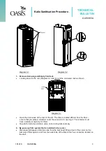
Expose filter system - removing front door panel from unit.  


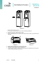
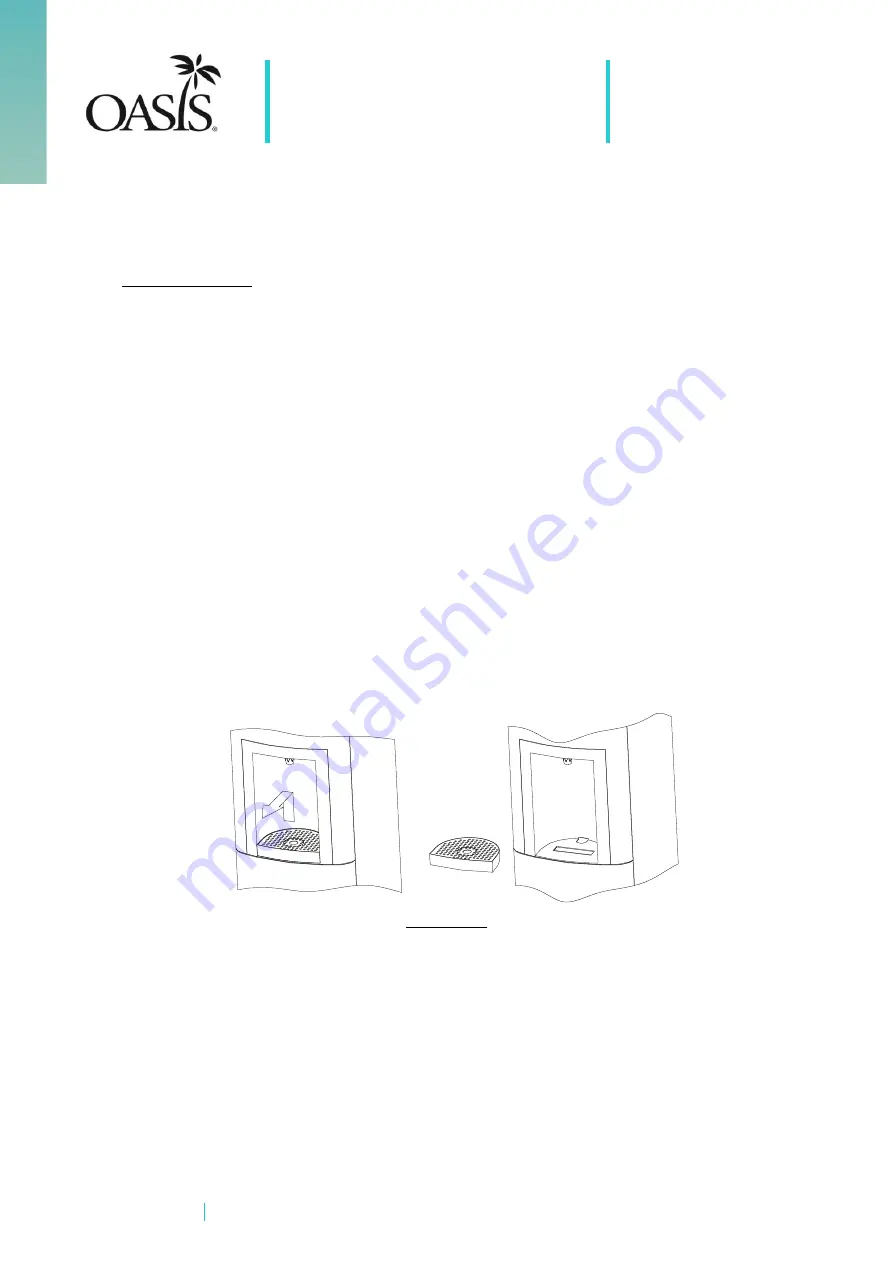
Lift out and remove the drip tray. (Diagram 3.1) 


Depress the clip visible through the slot in the alcove and swivel the door forward. (Diagram 
3.2) 


Diagram 3.1 

Summary of Contents for Kalix

Page 1: ...al head screw driver Sellotape Empty sanitizing filter unit Replacement filter media Replacement blue tubing 4000mm knife to cut lengths Cable ties x 4 Container for emptying contaminated cooler capac...

Page 2: ...ee piece by removing top of cooler Remove the top from the unit remove the two screws at the rear of the top and lift off the lid assembly Diagram 4 1 Diagram 4 2 4 Expose bulk head fitting by removin...

Page 3: ...is located 280mm from the floor ensure that you place a container under the valve prior to opening it The container must have a minimum capacity of 2 liters Re attach inlet tube and drain valve once...

Page 4: ...zation solution ensure all air is removed from system Once all air is removed dispense approx 300ml of water from cold side only Turn off mains water supply on cooler 9 Fill cook side of cooler with s...

Page 5: ...iagram 12 1 Diagram 12 2 Unscrew spout from water outlet Diagram 12 1 Remove blue tubing between water outlet and solenoids on cook and cold sides Diagram 12 2 Remove water outlet from unit Undo cable...

Page 6: ...rts thoroughly with clean water Place spout water outlet Inch reducers Tee piece and bulk head fitting in sanitization solution Ensure that the check valves remain open while parts are being sanitized...

Page 7: ...both the small and large bristle brush Rinse parts with clean water Diagram 12 6 Separate mounting bracket from filter head Wash in mild soap and water using the small bristle brush to clean the inter...

Page 8: ...sanitization solution for a further 10 minutes Remove all parts from sanitization solution and rinse thoroughly under a tap 12 Re install additional parts Diagram 13 1 Diagram 13 2 Using replacement f...

Page 9: ...outlet assembly with Inch reducers and place in original position Attach spout to water outlet and tighten into position Diagram 13 6 Re attach new tubing to Water outlet on cook and cold sides Reass...

Page 10: ...alix as per Diagram 14 3 Slide top over push buttons then secure in position via two screws at the back of the cooler Ensure cup dispenser is firmly in position before securing screws Return filter co...

Reviews: