background image

OBERHEIM GM 1000

Digital Signal Processor

- 143 -

Enables or disables reception/transmission of continuous controls in real time (also
depending on the value set in the FILTERS ON parameter).  When the parameter is set as
ON, the GM 1000 responds to this type of command.
Sys Ex parameter: Range, ON, OFF, ALL (ON, OFF).

Enables or disables reception/transmission of exclusive system Messages which allow
data exchanges or communications with the optional Oberheim FC 3000 remote control
(also depending on the value set in the FILTERS ON parameter).  Select ON to activate
the sys ex exchange function.

Clock/Panel parameter.  Range: ON, OFF.

The Clock parameter present when the value selected for FILTERS ON is IN allows the
user to enable or disable reception of the Midi Realtime Clock, meaning the control which
allows Midi synchronization of the BPM parameter of the Metronome Delay effect. When
the FILTERS ON value is OUT the Panel function becomes available and replaces the
Clock parameter on the display. With the Panel parameter on ON any operation performed
on the GM 1000 panel is encoded and made available in the form of exclusive system
messages in the MIDI OUT output. One use of this function may be to allow a series of
editing operations to be saved by Midi on a sequencer, ready for review later on the LCD
display or playback during a performance together with the musical sequence, to give a
visual check on the modifications made to it. It is also possible to insert modifications to
the sound in a performance in real time, in a way similar to the procedure used for the
analogue synthesizers without memory in use in the 'Seventies. However, in this case the
changes are made automatically without interfering with the musician's performance, at the
correct time and with mathematical precision, by a Midi digital system, which even allows
an immediate visual check on the modifications on the display.

  CAUTION !!: 

for correct recording and playback of a sequence which contains video

page changes, the main video page must appear on the GM 1000 screen in PLAY
MODE.  This must be remembered both when starting to record and when playing back.

Fc1 and Fc2 parameters.  Range: Y, N (Y=yes, N=no)

These set whether or not the foot controllers are to be active.  The bypass key can be
used to activate (ball solid) or disactivate (ball hollow) one or two foot controller(s),
obtaining all the possible combinations in succession.

The second edit page contains:

BYPASS, FC1, FC2, TUNER, CMP, DST, EQ, QMP, MOD, SP1, SP2, DLY, REV
parameters.  Range: 0 - 31, 64 - 119.

With these parameters, the user can set the Control Change value which will activate the
Bypass function if selected, the function assigned to Foot Controller 1 and 2 (programmed
in the Midi Foot Controller page, to which users should refer for any explanations), or
activate or disable one group in the effects chain.

Preset function.

Summary of Contents for GM-1000

Page 1: ...24 BIT DIGITAL SIGNAL PROCESSOR GM 1000 OPERATING MANUAL...

Page 2: ...batnub washbowl kitchen sink in a wet basement or near a swimming pool or the like 4 This product either alone or in combination with an amplifier and headphones or speakers may be capable of producin...

Page 3: ...Play mode 4 1 Keys and controls page 88 4 2 Selecting a memorized patch page 89 4 3 Programming page 89 5 Edit mode 5 1 Keys and controls page 91 5 2 Master level page 93 5 3 Memorizing a patch page...

Page 4: ...1 Tuner page 146 8 2 Analyzer page 147 9 Tips and Tricks 9 1 Level and digital technology page 150 9 2 Programming page 151 9 3 Writing the patches page 151 10 Initialization procedure 10 1 Factory se...

Page 5: ...ets monitors etc Never insert foreign bodies or liquids of any kind inside the instrument for any reason Never use solvents on the instrument s finishes To clean use only a soft cloth dipped in water...

Page 6: ...e 6 Guitar Input dedicated input connector for a guitar 7 Input Level regulates the amount of signal supplied as input to the GM 1000 The setting applies to both the front and rear connectors 8 Midi m...

Page 7: ...s 23 Midi Out five pin DIN connector for transmission of Midi messages generated by the GM 1000 24 L Mono R Input jacks for connection of a remote source to the GM 1000 There is a choice between a ste...

Page 8: ...screened cables make the audio connections first and then the mains connection Mixer Send Return P A System P A System A C current Foot switches P A System or Ampli P A System or Ampli Keyboard Mixer...

Page 9: ...apt the output volume to that of the equipment connected to the OUTPUT S Since this parameter can also be memorized more details of how it operates will be described in later sections Digital technolo...

Page 10: ...re obtained by means of more than forty algorithms and are arranged into categories or GROUPS Each group is able to contain up to 6 different effects of the user s choice and only one of them can be m...

Page 11: ...Proc Overdrive Crunch Mono Para Guitar 5 Bands Gra Stereo Para Bass Amp Flanger Phaser Step Phaser Tremolo Vibrato Comb Filter Dbl Chorus Ring Mod Auto Pan Fade In 3 V Ped Shift Custom Shift 4 Voi Cho...

Page 12: ...lue or anti clockwise to decrease The encoder works dynamically in other words the speed at which it is turned establishes the speed at which the selected value is varied General bypass To listen to t...

Page 13: ...suitable to requirements is obtained CAUTION an displayed on the right of the words play mode indicates that this modification has not been memorized in the patch To make the modification permanent r...

Page 14: ...ly one with values between 0 and 64 will be the DRIVE distortion intensity value which is certainly the most significant parameter in the group concerned To modify the operating level of a group Use t...

Page 15: ...e explained 5 1 KEYS AND CONTROLS For use of the CURSOR keys and the VALUE encoder see PLAY MODE section Edit and Exit keys The EDIT key gives access to the EDIT pages Once the EDIT function has been...

Page 16: ...key This key activates the patch writing function WRITE MODE described later in point 5 3 MEMORIZING A PATCH There are also cases when this key assumes different functions These will be displayed in l...

Page 17: ...is underlined by the word LEVELS on the display against the COMPARE key Press EXIT to return to the main video page in the edit pages it activates the sound compare function In other words it allows t...

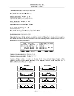
Page 18: ...offers the current location To modify the bank and or the location use the CURSOR keys and the VALUE encoder To change the name of the patch press the flashing Utility NAME key to display select the...

Page 19: ...effect you require using the CURSOR keys and then press the EDIT key We have emphasized this procedure because the fact that another effect is highlighted by the cursor might mislead you unless this o...

Page 20: ...45 Sets the level of the input signal below which the compression effect will operate Attack parameter Range 0 100 The attack parameter allows the user to set a delay in activation of the compression...

Page 21: ...put signal below which the expansion effect comes into operation The range goes from 0 corresponding to a level of about 14 dB to 45 corresponding to a level of about 48 dB Hold Time parameter Range 0...

Page 22: ...t of the effects chain Attack parameter Range 0 100 Sets the time for which the compressor acts on the signal attack Bass parameter Range 0 100 Regulates the low section of the crossover B to M parame...

Page 23: ...whether the control signal is given by the sum of the left hand and right hand signals or only by the right hand single In the second case the audio signal is the left hand signal only Ratio parameter...

Page 24: ...ed by the modes vary quite widely Dynamic Loudness adds the frequencies selected to the crossover depending on the total level of the input signal Spectral Compressor compresses the frequencies select...

Page 25: ...ies The information given in the description of the DeEsser applies 6 2 DISTORTION DST DISTORTION This is absolutely the best known guitar effect It simulates the distortion of an amplifier which has...

Page 26: ...ve parameter Range 0 64 Controls the intensity of the effect HDamp parameter Range 4K0 3K2 2K5 2K0 1K6 Displays the cut off frequency used by a filter which eliminates all the frequencies above the on...

Page 27: ...nt between 14dB and 14dB Level parameter Range 0 100 Regulates the level of the output signal in the context of the effects chain MONO PARAMETRIC This is a parametric equalizer in which the user can m...

Page 28: ...ge 0 100 Regulates the level of the output signal in the context of the effects chain Peaking 1 6 filters Frequency Range 100 140 200 280 400 560 800 1k0 1k4 2k0 2k8 4k0 5k6 8k0 Hz Bandwith Q Range 0...

Page 29: ...b 14dB This filter is also differentiated For the enhancement zone it uses a Presence filter centred on 2100 Hz while for attenuation it uses another working on 10 KHz Level parameter Range 0 100 Regu...

Page 30: ...e parameters which can be modified are the working frequency and the trigger level High Shelve filter Freq Range 1k5 2k1 3k0 4k2 6k0 8k5 12k Hz Enhancement Attenuation Range 14dB 14dB This filter of s...

Page 31: ...cy response created by the amplifier s cabinet and speakers When a multieffect device is connected directly to the mixer of a P A system i e without using the amplifier this component is lacking The m...

Page 32: ...ffects chain BASS AMP Amp Type parameter Range DI V S HV This parameter is used to set the type of bass amplifier to be simulated The values this field is able to assume are 1 DI BOX DI BOX linear res...

Page 33: ...two lines one remains unchanged while the tuning of the other is modified slightly in a cyclical way modulation The two lines are then mixed and the resulting sound has more body is richer and seems r...

Page 34: ...itted by a jet during take off Type parameter Range STEREO MONO DOUBLE The parameter which selects the type of Flanger Rate parameter Range 0 100 Sets the modulation frequency Depth parameter Range 0...

Page 35: ...milliseconds after the other The resulting sound created as frequencies are added and removed is similar to that obtained with the Flanger although in this case it is a little more tenuous and thinne...

Page 36: ...100 This parameter regulates the depth of the modulation Manual parameter Range 0 100 This parameter sets the modulation delay Emphasis parameter Range 0 100 The parameter governs the amount of feedb...

Page 37: ...f the up and down fronts of a trapezoidal waveform Panpot parameter Range 0 100 This parameter adjusts the relative time stagger between the Left and Right channels Speed parameter Range 0 100 Sets th...

Page 38: ...ts name It is obtained by means of a filter which is opened and closed automatically by the level of the signal itself or by means of a remote pedal Trigger parameter Range AUTO PRE AUTO POST PEDAL FC...

Page 39: ...ut signal in the context of the effects chain COMB FILTER This is a comb filter with two lines which provide two resonance frequency patterns It is the equivalent of a flanger with its modulation lock...

Page 40: ...Sets the frequency of each of the two modulants Depth 1 and Depth 2 parameter Range 0 100 This parameter regulates the modulation depth for each modulant Pre Delay parameter Range 0 100 This paramete...

Page 41: ...ange 0 100 The parameter regulates the modulation depth Direct parameter Range 0 100 This parameter regulates the level of the direct signal Effect parameter Range 0 100 Regulates the level of the eff...

Page 42: ...s the level of the output signal in the context of the effects chain FADE IN An effect which consists of a gradual rise in the volume attenuating or eliminating perception of the start of the input si...

Page 43: ...a line which can be freely tuned by the user to the original signal This effect is a two line version of the Pitch Shifter available in two versions both with Pre Delay and Feedback a first version i...

Page 44: ...equency shift required subdivided into a roughly accurate part set in semitones Shift and a fine part set in hundredths of a tone Fine Pre Delay parameter Range 0 100 in case of Stereo 0 300 in case o...

Page 45: ...vel parameter Range 0 100 Regulates the level of the individual shifting lines Direct parameter Range 0 100 Regulates the level of the direct signal Master parameter Range 0 100 Regulates the level of...

Page 46: ...rameter Range 1 4 Selects which of the 4 lines is to be modified Rate parameter Range 0 100 Regulates the modulation speed of the selected voice Pre Delay parameter Range 0 100 This parameter sets the...

Page 47: ...n the context of the effects chain Hi Section Slow Rate parameter Range 0 100 Hi Section Fast Rate parameter Range 0 100 Lo Section Slow Rate parameter Range 0 100 Hi Section Fast Rate parameter Range...

Page 48: ...Sets the input signal threshold above which the effect is activated Level parameter Range 0 100 Regulates the level of the output signal in the context of the effects chain Xfreq parameter Range 63 8...

Page 49: ...put of the delay line and thus the time after which the repetition ceases Hi Damp parameter Range None 20K 19K 18K 17K 16K 14K5 12K5 11K5 10K 9K 8K 6K35 5K05 4K 2K 1K Displays the cut off frequency of...

Page 50: ...n relation to the speed of the song the musician is performing In practice the length of the delay will be set by measuring the time which passes between two consecutive pressures on the pedal TAP DEL...

Page 51: ...The mechanism has already been explained with regard to the Standard Delay Control of the TAP pedal The TAP pedal is used to enter the Feedback Time or repetition time not by manual editing but in re...

Page 52: ...s parameter is very useful for the creation of a number of unusual effects Hi Damp parameter Range None 20K 19K 18K 17K 16K 14K5 12K5 11K5 10K 9K 8K 6K35 5K05 4K 2K 1K Displays the cut off frequency o...

Page 53: ...vel of the selected line Hi Damp parameter Range None 20K 19K 18K 17K 16K 14K5 12K5 11K5 10K 9K 8K 6K35 5K05 4K 2K 1K Displays the cut off frequency of a filter which eliminates from the taps all the...

Page 54: ...r Range 0 100 Regulates the quantity of signal returned to the input of the delay line selected thus the time before the repetitions cease Hi Damp parameter Range None 20K 19K 18K 17K 16K 14K5 12K5 11...

Page 55: ...et the delay time on the basis of the metronome speed of the song Delay parameter Range 1 2 Selects on which of the two lines the modifications are to be made Pattern Notes Value parameter Range 1 4 1...

Page 56: ...s of natural sound together Direct sound in practice this is the sound emitted by the sound source which reaches our ears directly without ever being reflected If the value of this parameter is high e...

Page 57: ...10K 9K 8K 6K35 5K05 4K 2K 1K Displays the cut off frequency of a filter which eliminates all the frequencies higher than the one set Direct parameter Range 0 100 Regulates the level of the input signa...

Page 58: ...e 1k5 2k1 3k0 4k2 6k0 8k5 12k Hz Boost Cut Range 14db 14dB For this section refer to the explanations supplied in the section on the parametric equalizer These controls act on equalization of the late...

Page 59: ...e 0 100 Regulates the level of the output signal in the context of the effects chain in this case the sum of the processed sound and the direct sound mixed by means of the EFFECT LEVEL and DIRECT LEVE...

Page 60: ...gnal with the end of the early reflections pattern as time reference Accent Delay parameter Range 0 200 ms Regulates the delay of the repetition known as Accent see above on both channels Direct Eq Lo...

Page 61: ...s of the reverberation chamber to be simulated Master parameter Range 0 100 Regulates the level of the output signal in the context of the effects chain Source X parameter Range 0 Chamber Width Source...

Page 62: ...om 0 to 360 at intervals of 5 The last three parameters set the virtual polar diagrams of the listening points The two diagrams which follow show two examples intended to make the use of these control...

Page 63: ...rameter Range None 20K 19K 18K 17K 16K 14K5 12K5 11K5 10K 9K 8K 6K35 5K05 4K 2K 1K Displays the cut off frequency of a filter which eliminates all the frequencies higher than the one set from the reve...

Page 64: ...ircuit is broken when the signal passes above the threshold set by the Threshold parameter Release Time parameter Range 0 10 Sets the amount of time which will pass before the circuit is closed when t...

Page 65: ...used Parameter parameter Selects the parameter to be modified using the foot controller In this case the range depends on the group selected since as we have seen in EDIT MODE the parameters often va...

Page 66: ...cuts out reception Device Id parameter Range 1 2 3 4 5 6 7 8 9 10 11 12 13 14 15 16 Allows the user to set the device identification number from 1 to 16 if more than one GM 1000 devices are used conne...

Page 67: ...k during a performance together with the musical sequence to give a visual check on the modifications made to it It is also possible to insert modifications to the sound in a performance in real time...

Page 68: ...s when the selection is made during a live performance Program Change Nr parameter Range 1 128 Allows the user to set the number of the Program Change to be used Location Bank parameter Range A B C Al...

Page 69: ...hen the display is showing the PLAY MODE the multieffects unit will reply with a message which shows that data reception is in progress 7 4 MIDI MONITOR The MIDI MONITOR function enables the flow of t...

Page 70: ...tuning for 4 string bass OPEN G open G major tuning OPEN D open D major tuning OPEN Em open E minor tuning Dropped D guitar tuning with the 6th string one tone flat D CAUTION the use of an instrument...

Page 71: ...the main applications that this function of the GM 1000 is destined to perform is without doubt the frequency response measurement in enviroments of audio amplification systems In fact is possible by...

Page 72: ...nvolved the use of a function that generated a high volume control signal an unexpected emission of this signal could happen with dangerous consequences for the user s hearing To avoid this happening...

Page 73: ...esults of the analysis or SELECT Edit to compare the current analysis with that in the memory selected by default all the Template memories are empty Proceeding with the analysis the display will show...

Page 74: ...earing in mind the gain in amplification that the effect produces In order to realize what percentage of gain is introduced by a selected effect you are advised to use the LOCAL BYPASS function under...

Page 75: ...jacent locations or in locations with the same number but in different banks for example C121 and C122 or C121 and D121 for convenience the first patch is called SOURCE and the second DESTINATION 2 Ch...

Page 76: ...controller programming It can happen that one or both the Foot Controllers are shown to be assigned to the WHA effect on the SP 1 group even though it is in Bypass or deactivated In this case it is n...

Page 77: ...VARIABLES to be used only if the system becomes blocked PANIC The basic values of a number of parameters of the control software will be restored if the contents of the memory have been contaminated...

Page 78: ...ice dialogue in graphic or text form Dsp abbreviation of Digital Signal Processor Edit function for modification of the device parameters Foot Controller type of pedal control unit Allows commands to...

Page 79: ...LAY MEMORY 768 KWORDS 17 41 ms DATA ALU PROCESSING 33 9 MIPS ADDRESS ALU PROCESSING 39 5 MIPS MULTIPLIER SIZE 32 x 24 BITS MEMORY CAPACITY 4 BANKS X 128 PROGRAMS 512 TOTAL PROGRAMS TOOLS TUNER CONCERT...

Page 80: ...200 OHM LINE OUT REAR JACK CONNECTORS 2x UNBALANCED JACK TS MIN LOAD IMPEDENCE 600 OHM NOMINAL OUT LEVEL 4 DMB LINE OUT REAR CANNON CONNECTORS 2x BALANCED CANNON XLR MIN LOAD IMPEDENCE 600 OHM NOMINA...

Page 81: ...7 0 127 VELOCITY Note ON Note OFF X X O X AFTER Key s TOUCH Ch s X X X X PITCH BENDER X X CONTROL 7 CHANGE 64 66 67 91 93 O O O O O O O O O O O O Volume Hold Sostenuto Soft Reverb Chorus PROGRAM CHANG...

Page 82: ......

Page 83: ...ating system since this version of the manual was completed The information contained in this version of the version of the owner s manual supercedes all previous version NOTE This equipment has been...

Page 84: ......

Reviews: