Installation Guide /
Guía de instalación
for Oberon Model 1021
-
00 & 1021
-
00
-
ANTPLATE
para Modelo Oberon 1021
-
00 & 1021
-
00
-
ANTPLATE
Mounting Solutions for WiFi Access Points
"Oberon" and all other marks where denoted are trademarks of Oberon Inc.
©
1999
-
2020 Oberon Incorporated. All rights reserved.
"Oberon" y todas las demás marcas donde se denotan son marcas comerciales de Oberon Inc. ©1999
-
2020 Oberon Incorporated. Todos los derechos reserve.
EPN 3200 & 3364
-
6/15/2020
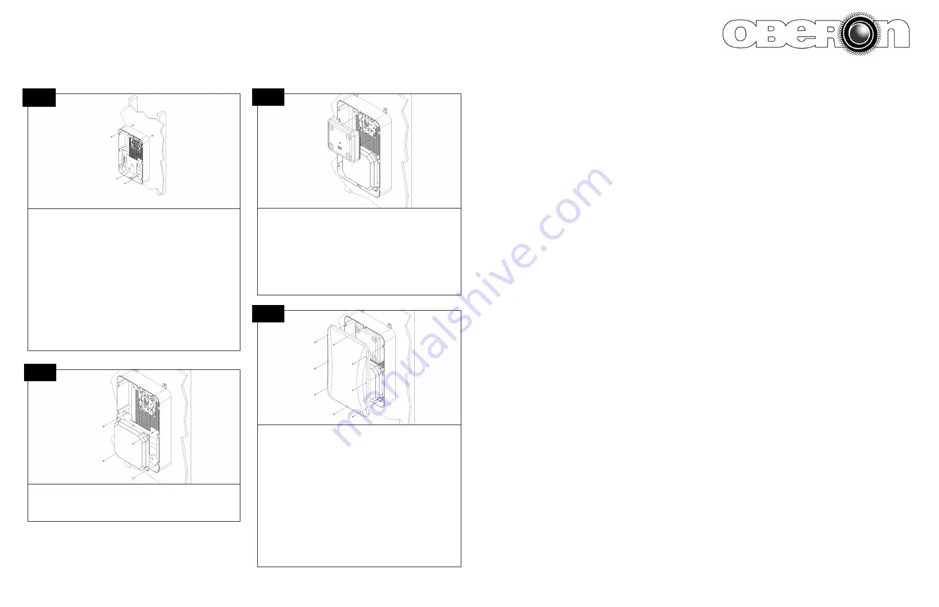
Attach the antenna with the provided #8 x 5/8” screws for Cisco Antennas,
or #6 x 1/2” Screws for Aruba Networks and other antennas.
Conecte la antena con los tornillos suministrados #8 x 5/8" para Antenas de
Cisco, o con los Tornillos #6 x 1/2" para Aruba Networks y otras antenas.
4
Attach any cables to the Access Point. Then fasten to the installed AP
mounting bracket or T
-
Bar Bracket. Some Access Points may need to be
directly mounted to the internal panel by drilling pilot holes.
(For
-
ANTPLATE SKUs ONLY)
Connect the antenna to the Access
Point.
Conecte los cables al punto de acceso. Luego, fíjelo al soporte de mon-
taje AP instalado o al soporte de la barra en T. Es posible que algunos
puntos de acceso deban montarse directamente en el panel interno
taladrando agujeros piloto.
(SOLO PARA SKU
-
ANTPLATE)
Conecte la antena al punto de acceso.
5
(For
-
ANTPLATE SKUs ONLY)
Articulate the antenna for proper align-
ment and tighten the hex screws.
After the cables are attached, place the lid on the base then secure it
with the eight (8) M4 x 20 mm pan head machine screws or tamper re-
sistant Torx screws provided with the enclosure. The screws should be
tightened to 8 in
-
lbs to properly seal the enclosure. Do not over tighten.
Make sure the gasket is properly seated prior to tightening.
The installation is now complete.
(SOLO PARA SKU
-
ANTPLATE)
Articule la antena para una alineación
adecuada y apriete los tornillos hexagonales.
Después de conectar los cables, coloque la tapa en la base y luego
asegúrela con los ocho (8) tornillos de cabeza plana M4 x 20 mm o los
tornillos Torx resistentes a la manipulación provistos con el gabinete.
Los tornillos deben apretarse a 8 in
-
lb para sellar adecuadamente el
gabinete. No apriete demasiado. Asegúrese de que la junta esté asen-
tada correctamente antes de apretarla.
La instalación está completa.
6
3b
The enclosure may also be directly mounted to a surface without the mount-
ing feet. Drill 1/4” holes through the box in four (4) corners. Use four (4) #10
x 2” screws (not included) and suitable anchor hardware (not included) to
fasten to the wall or ceiling.
(For installations that require cushioning washers)
Insert a cushioning
washer between the box and surface in each corner.
Tighten screws uniformly around the box so it does not flex. Properly seal
any openings to maintain NEMA 4 rating.
El recinto también se puede montar directamente en una superficie sin los
pies de montaje. Taladre agujeros de 1/4 ”a través de la caja en cuatro (4)
esquinas. Use cuatro (4) tornillos #10 x 2” (no incluidos) y herrajes de ancla-
je adecuados (no incluidos) para fijarlos a la pared o al techo.
(Para instalaciones que requieren arandelas de amortiguación)
Inserte
una arandela de amortiguación entre la caja y la superficie en cada esquina.
Apriete los tornillos de manera uniforme alrededor de la caja para que no se
doble. Selle adecuadamente las aberturas para mantener la clasificación
NEMA 4.


