Installation Guide /
Guía de instalación
for Oberon Model 1026
-
XX
para Modelo Oberon 1026
-
XX
Mounting Solutions for WiFi Access Points
"Oberon" and all other marks where denoted are trademarks of Oberon Inc.
©
1999
-
2022 Oberon Incorporated. All rights reserved.
"Oberon" y todas las demás marcas donde se denotan son marcas comerciales de Oberon Inc. ©1999
-
2022 Oberon Incorporated. Todos los derechos reserve.
EPN 2872, 2873, 2874, 2875, 2876, 2877, 2878, 2879, 2880, 2881, 3562, 3563, 3564, 3565, 3566, 3567, 3568, 3569, 3570, 3571, 4257, 4261, 4285, 4293, 4395, 4396, 4397, 4398, 4440, & 4441
-
Rev 5/4/2022
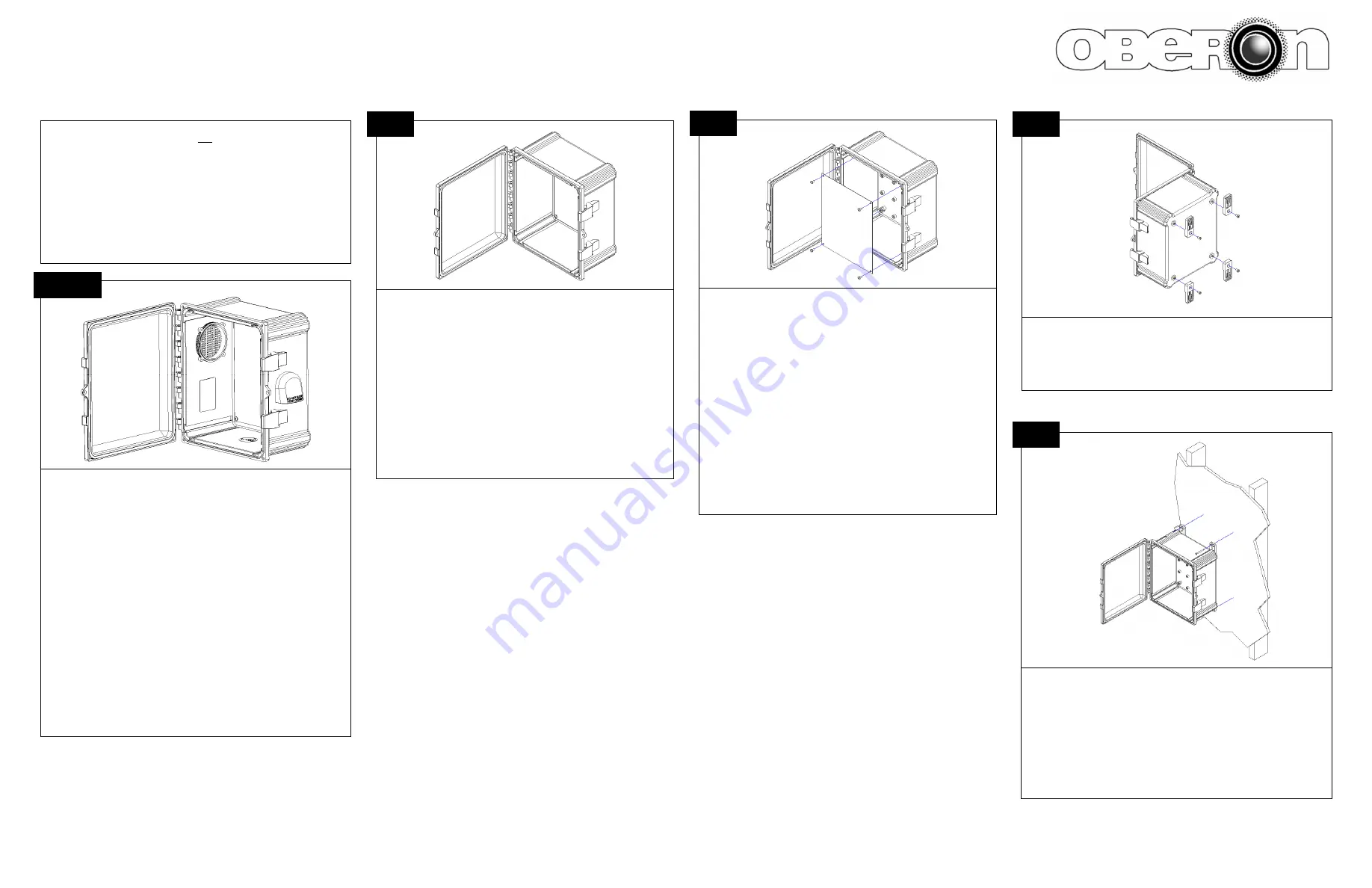
Find a flat work surface to assemble the enclosure, access point’s
mounting panel, and antenna(s) prior to mounting on wall.
Place the enclosure assembly on the work surface with the door open.
Drill access holes into the bottom of the enclosure. These will be used
later to bring cabling into the enclosure, so the holes should be sized to
match the grommets (not included) that will be used for cabling.
Busque una superficie de trabajo plana para ensamblar el gabinete, el
panel de montaje del punto de acceso y la(s) antena(s) antes de montar-
lo en la pared.
Coloque el ensamblaje del gabinete en la superficie de trabajo con la
puerta abierta.
Taladre orificios de acceso en la parte inferior del gabinete. Estos se
usarán más adelante para llevar el cableado al gabinete, por lo que los
orificios deben tener un tamaño que coincida con los ojales (no inclui-
dos) que se usarán para el cableado.
1
Remove the four (4) #10 x 3/8 in. screws and lift the universal mounting
panel out of the 1026.
Before drilling any holes into the universal mounting panel, use the ac-
cess point and/or AP mounting bracket to determine where the holes are
to be made.
After drilling the holes into the universal mounting panel, either: 1) mount
the AP to the universal mounting panel using the machine screws includ-
ed with the AP, or 2) use self
-
tapping screws (not included) to mount the
AP mounting bracket to the universal mounting panel.
Quite los cuatro (4) tornillos #10 x 3/8 pulg. y levante el panel de montaje
universal para sacarlo del 1026.
Antes de perforar cualquier agujero en el panel de montaje universal,
use el punto de acceso y/o el soporte de montaje AP para determinar
dónde se harán los agujeros.
Después de perforar los orificios en el panel de montaje universal, haga
lo siguiente: 1) monte el AP en el panel de montaje universal usando los
tornillos para metales incluidos con el AP, o 2) use tornillos autorroscan-
tes (no incluidos) para montar el soporte de montaje del AP en el panel
de montaje universal.
2
Place the enclosure on the wall where it is to be installed (it is recommended
that you mount directly to a stud) and mark the screw locations. Use a mini-
mum of two (2) #10 x 2” (not included) or larger screws to secure the enclo-
sure in place. However, if there is no stud at the mounting location, it is rec-
ommended that you use a minimum of four (4) suitable anchors to secure
the enclosure in place.
Coloque el gabinete en la pared donde se instalará (se recomienda que lo
monte directamente en un montante) y marque la ubicación de los tornillos.
Use un mínimo de dos (2) tornillos #10 x 2” (no incluidos) o más grandes
para asegurar el gabinete en su lugar. Sin embargo, si no hay un montante
en la ubicación de montaje, se recomienda que use un mínimo de cuatro (4)
anclajes adecuados para asegurar el gabinete en su lugar.
4
If not integrated into the enclosure base, fasten the four (4) mounting feet to
the back of the enclosure using the 1/4”
-
20 x 1/2 in. Mounting Feet Screws
with 30 inch
-
pounds of torque.
Si no están integrados en la base del gabinete, fije los cuatro (4) pies de
montaje a la parte posterior del gabinete usando los tornillos de los pies de
montaje de 1/4”
-
20 x 1/2 pulg. con 30 pulgadas
-
libras de torque.
3
***The AP maximum operating temperature should be de
-
rated inside
the enclosure when solar loading is not present. The amount the AP is
de
-
rated depends on the size of the enclosure, and the power dissipa-
tion of the AP. The Model 1026 is light gray to reduce solar loading,
while painting the enclosure a darker color will increase solar loading.
Avoid mounting the 1026 where it is exposed to direct sunlight.
***La temperatura de funcionamiento máxima AP debe reducirse den-
tro del gabinete cuando no hay carga solar presente. La cantidad que
se reduce el AP depende del tamaño del gabinete y la disipación de
energía del AP. El Modelo 1026 es de color gris claro para reducir la
carga solar, mientras que pintar el gabinete de un color más oscuro
aumentará la carga solar. Evite montar el 1026 donde esté expuesto a
la luz solar directa.
NOTE (For All
-
V SKUs Only):
The enclosure has two (2) vents, one small
(60mm) vent and one large (80mm) vent. If additional airflow is desired,
mount a fan (not included) to one of the vents. A fan with a square 60mm
fan form factor should align with the 50.0mm x 50.0mm hole pattern molded
into the smaller vent. A fan with a square 80mm fan form factor should align
with the 71.5mm x 71.5mm hole pattern molded into the larger vent.
The
installer is responsible for determining which specific fan, if any, is
acceptable to use.
It is recommended that the installer determine a fan
only after considering criteria, including, but not limited to: air flow rating,
static pressure rating, bearing type, power rating (in Watts), current rating (in
Amps), voltage range, operating temperature range, RPM, and average
product lifespan.
NOTA (Solo para todos los SKU
-
V):
El gabinete tiene dos (2) respirade-
ros, uno pequeño (60mm) y uno grande (80mm). Si desea un flujo de aire
adicional, monte un ventilador (no incluido) en una de las rejillas de venti-
lación. Un ventilador con un factor de forma de ventilador cuadrado de 60
mm debe alinearse con el patrón de orificios de 50.0mm x 50.0mm
moldeado en la ventilación más pequeña. Un ventilador con un factor de
forma de ventilador cuadrado de 80mm debe alinearse con el patrón de
orificios de 71.5mm x 71.5mm moldeado en la ventilación más grande.
El
instalador es responsable de determinar qué ventilador específico, si
corresponde, es aceptable usar.
Se recomienda que el instalador deter-
mine un ventilador solo después de considerar criterios que incluyen, entre
otros: índice de flujo de aire, índice de presión estática, tipo de cojinete,
índice de potencia (en vatios), índice de corriente (en amperios), rango de
voltaje, rango de temperatura, RPM y vida útil promedio del producto.
NOTE


