background image

Alaris30 Installation Guide

Objet Confidential and Proprietary Information

15

4.1.1  Connect Cables

1.

Ensure


that


the


power


is


off


to


the


Server


workstation


and


to


the


Alaris30


printer.

2.

Plug


the


keyboard,


monitor


and


mouse


cables


into


their


respective


ports


on


the


KVM


Switch


(see


Figure


4–1).


The


keyboard


and


mouse


ports


are


labeled


with


icons


to


indicate


which


port


is


which.

Figure 4–1  KVM Switch Connections Overview

3.

Connect


the


cable


between


the


KVM


Switch


and


the


Server


workstation.


That


is,


connect


the


cable’s


KVM


Switch


D

type


connector


to


the


D

type


socket


on


the


switch


and


connect


the


cable’s


monitor


and


USB


connectors


to


the


relevant


sockets


on


the


Server


workstation


(see


Figure


4–2).

If the Server workstation has the “Keyboard Power On” function, unplug the Server 
workstation’s power cord.

Summary of Contents for Alaris30

Page 1: ...Alaris30 3 D Printer Installation Guide DOC 04006 September 2008 Objet Geometries Ltd...

Page 2: ......

Page 3: ...database or retrieval system without prior permission in writing from Objet Geometries Ltd September 2008 DOC 04006 Rev A Trademarks The following are registered trademarks of Objet Geometries Ltd Ob...

Page 4: ...al Material used for supporting the structure of models during production Alaris30 computer The computer built into the Alaris30 printer Alaris30 software Software running on the computer inside the A...

Page 5: ...chbox 14 4 1 1 Connect Cables 15 4 1 2 Switching between Computers 16 4 2 Connect Communication Cable 17 4 3 Prepare Power Cable 17 4 4 Visual Check of Cables and Cards 18 5 Setup Server Workstation A...

Page 6: ...ver Workstation Procedure 38 5 6 2 Alaris30 Computer Procedure 40 5 6 3 Verify Sharing Setup 42 5 7 Install Objet Studio on Server Workstation 42 5 8 Back Up Alaris30 Folder 42 6 Material Installation...

Page 7: ...switch page 14 Connect the server workstation computer to the printer page 17 Configure a point to point connection from the Server workstation to the printer page 19 Install Objet Studio with Job Ma...

Page 8: ...nspect the outside of the shipped package for damage Note the status of the tilt and shock detectors Figure 2 1 Tilt and Shock Detection If the outside of the package is damaged or the tilt and shock...

Page 9: ...ing pliers 3 Open the top cover of the package Figure 2 2 Top Cover Open 4 Remove the wooden corner supports 5 Lift up and remove the cover inside the package 6 Check the status of the shock detector...

Page 10: ...e 2 3 Alaris30 Printer Packing Material 9 Once the packing material is removed examine the Alaris30 printer for damage Give special attention to loose parts or cables to the UV protection glass and to...

Page 11: ...ormation 11 10 Carefully lift the Alaris30 printer off the pallet using a hand pallet truck and move the printer to its final location Objet recommends that the customer keep and store the pallet the...

Page 12: ...12 3 Axis Locks and Print Head Cover The following tool is required for this chapter Cutting pliers 3 1 Release X axis Cut and remove the cable ties attached to the X axis belt and print head Figure...

Page 13: ...e cut remove the heads protecting cover shown in Figure 3 2 by doing the following Open the heads protecting cover Pull the cover from the bottom sideways off the print head Be careful and use extra c...

Page 14: ...omes with cables for connecting computers to the switch One end of the cable which is connected to the KVM switch consists of a D type connector and an audio connector The other end of the cable has a...

Page 15: ...ard and mouse ports are labeled with icons to indicate which port is which Figure 4 1 KVM Switch Connections Overview 3 Connect the cable between the KVM Switch and the Server workstation That is conn...

Page 16: ...ect the cable s monitor and the USB connectors to the relevant sockets at the back of the printer 4 1 2 Switching between Computers The switches on the front of the KVM can be used to switch control b...

Page 17: ...on the Server workstation 4 3 Prepare Power Cable Attach or have the customer s electrical personnel attach the appropriate power plug to the power cable from the back of the printer The minus key mus...

Page 18: ...Alaris30 Installation Guide Objet Confidential and Proprietary Information 18 4 4 Visual Check of Cables and Cards Open the printer and visually check that all the cards and cables are seated properly...

Page 19: ...er workstation and the Alaris30 computer see page 20 Disabling software and Windows options on the Server workstation Automatic updates see page 34 Power Saver see page 35 Antivirus see page 38 Firewa...

Page 20: ...30 printer 1 Press at the same time Alt Ctrl Delete twice 2 Login to the Alaris30 printer as administrator 5 2 Setup Point to Point Communication 5 2 1 Information from Server Workstation 1 Open the S...

Page 21: ...t Confidential and Proprietary Information 21 2 Select the Computer Name tab Figure 5 2 System Properties Window Computer Name Tab 3 Click Change The Computer Name Changes window opens Figure 5 3 Comp...

Page 22: ...main name 5 Click Cancel 6 Click Cancel in the System Properties window 5 2 2 Alaris30 Computer Setup 1 Right click on My Computer on the Desktop and select Properties from the drop down menu The Syst...

Page 23: ...igure 5 5 Computer Name Changes Window 4 Select Workgroup 5 Type the Domain name of the Server workstation into the Workgroup field 6 Write down the name of the Alaris30 computer 7 Click OK A Welcome...

Page 24: ...OK 10 Click OK in the Computer Name Changes window The System Settings Change dialog box opens Figure 5 8 Restart Computer Message 11 Click Yes The Alaris30 computer reboots 12 Login as administrator...

Page 25: ...roprietary Information 25 Figure 5 9 Network Connections Window 14 Right click on Local Area Connection and select Properties from the drop down menu The Local Area Connection Properties window opens...

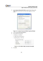
Page 26: ...nd click Properties The Internet Protocol TCP IP Properties window opens Figure 5 11 Internet Protocol TCP IP Properties Window 16 Select Use the following IP address 17 Set up the following values IP...

Page 27: ...4 Set the local time date and time zone 25 Reboot the Alaris30 computer 5 2 3 Server Workstation Setup 1 Open the Start menu on the Server workstation right click on My Network Places and select Prope...

Page 28: ...ial and Proprietary Information 28 2 Right click on the unconnected Local Area Connection icon and select Properties from the drop down menu The Local Area Connection Properties window opens Figure 5...

Page 29: ...list and click Properties The Internet Protocol TCP IP Properties window opens Figure 5 15 Internet Protocol TCP IP Properties Window 4 Select Use the following IP address 5 Set up the following value...

Page 30: ...ab Alaris30_name where the tab represents pressing the Tab key and Alaris30_name is the name of the Alaris30 computer 11 Save and close the hosts file 5 2 4 Disable Firewall If a firewall is running o...

Page 31: ...Confidential and Proprietary Information 31 2 Double click Windows Firewall The Windows Firewall window opens Figure 5 17 Windows Firewall Window 3 Select Off 4 Click OK 5 Close the Control Panel wind...

Page 32: ...do the following 1 Select Run from the Start menu 2 Type cmd in the Open field and click OK 3 Type ipconfig and press Enter The IP address information should be displayed Figure 5 18 Example Ipconfig...

Page 33: ...0_name is the name of the Alaris30 computer and press Enter If you get a reply the name of the Alaris30 computer has been recognized by the ping command On the Alaris30 computer do the following 1 Sel...

Page 34: ...atic Updates for Windows On the Server workstation do the following 1 Select Control Panel from the Start menu The Control Panel window opens 2 Double click Automatic Updates The Automatic Updates win...

Page 35: ...l and Proprietary Information 35 5 4 Disable Power Saver On the Server workstation do the following 1 Right click on the Desktop and select Properties from the pop up menu The Display Properties windo...

Page 36: ...Alaris30 Installation Guide Objet Confidential and Proprietary Information 36 2 Select the Screen Saver tab Figure 5 22 Screen Saver Tab...

Page 37: ...The Power Options Properties window opens Figure 5 23 Power Options Properties Window 4 Select Always On from the Power schemes drop down menu 5 Select OK 6 Select OK in the Display Properties window...

Page 38: ...running on the Server workstation disable the following Periodic virus checking Auto updates 5 6 Setup Sharing 5 6 1 Server Workstation Procedure 1 Create a new folder named Objet on the C drive of th...

Page 39: ...tallation Guide Objet Confidential and Proprietary Information 39 2 Right click on the Objet folder and select Properties from the pop up menu The Objet Properties window opens Figure 5 24 Objet Prope...

Page 40: ...jet Properties Window Sharing Tab 4 Select Share this folder 5 Click OK 5 6 2 Alaris30 Computer Procedure 1 Open the Start menu on the Alaris30 computer and select My Computer The My Computer window o...

Page 41: ...Alaris30 Installation Guide Objet Confidential and Proprietary Information 41 Figure 5 26 Local Disk Properties Window 3 Select the Sharing tab Figure 5 27 Local Disk Properties Window Sharing Tab...

Page 42: ...the Desktop computer 5 7 Install Objet Studio on Server Workstation The User name used to login into the Server workstation for the Objet Studio installation must have full Administrator rights Refer...

Page 43: ...all the tests pass successfully 2 After the tests pass successfully print a customer model 6 3 Model Scaling This procedure describes how to enter the scaling specifications These specifications ensu...

Page 44: ...ry Information 44 1 From the File menu select Machine Properties 2 Enter your password to continue 3 In the Machine Properties dialog box display the Model Accuracy tab 4 In the Required Measurement f...

Page 45: ...Desktop of the printer computer open the following file Open Scaling txt 6 From the Open Scaling file copy the X mm measurement and paste it into the X mm Actual Measurement field copy the Y mm measu...

Reviews: