background image

DOC-24000 Rev. C

7–31

Objet30 User Guide

Aligning the 

Print Heads

You


should


check


the


alignment


of


the


print


heads—


once


a


month

if


model


quality


is


not


acceptable


even


after


cleaning


the


orifice


plate


on


the


bottom


of


the


print


block


(see


“Cleaning


the


Print


Heads”


on


page 7

22)

The


head

alignment


procedure


takes


about


20


minutes.

To check the alignment of the print heads:

1. Prepare—

a


transparency


sheet,


at


least


10


×


16


centimeters


in


size


(4.5 ×


6.5


inches)—about


one

quarter


of


the


standard


A

4


or


Letter


size

any


type


of


sticky


tape,


to


fasten


the


transparency


sheet


to


the


build


tray

2. Start


the


Head


Alignment


wizard,


from


the


Objet30


Options


menu


(see


figure 7

33


on


page 26).

3. Click


Next


to


begin,


and


close


the


cover.

4. In


the


wizard


screen,


select


the


check


box


to


confirm


that


the


cover


is


closed,


and


click


Next

.

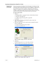
Figure 7-43: 

Door is closed

 confirmation screen

5. When


instructed


to


do


so,


place


the


transparency


on


the


build


tray—


near


the


left


and


rear


edges


of


the


tray,


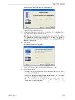
as


shown


in


the


following


figure.

Figure 7-44: Positioning the transparency on the build tray

6. Make


sure


that


the


transparency


sheet


is


lying


flat,


and


tape


it


to


the


tray.

Summary of Contents for Alaris30

Page 1: ...User Guide English Objet30 3 D Printer System ...

Page 2: ......

Page 3: ...ense The 3 D printer referred to in this guide contains a transmitter module FCC ID YH6 RFID NOTE Objet Geometries is not responsible for radio or TV interference caused by unauthorized modification to this equipment Such modification could void the user s authority to operate the equipment Equipment Recycling In the European Union this symbol indicates that when the last user wishes to discard a ...

Page 4: ...he following U S patents 5 386 500 6 259 962 6 569 373 6 658 314 6 850 334 7 183 335 7 209 797 7 225 045 7 364 686 7 369 915 7 479 510 7 500 846 7 604 768 7 628 857 7 658 976 7 725 209 Objet Geometries Ltd http www objet com DOC 24000 Revision C July 2011 ...

Page 5: ...ngestion 2 6 Inhalation 2 6 Waste Disposal 2 7 3 Introducing the Objet30 3 D Printing System Work Configurations 3 2 Source Files 3 3 STL Files 3 3 SLC Files 3 3 Printing Materials 3 4 Available Materials 3 4 Storage 3 4 Shelf Life 3 5 Exposure to Light 3 5 Safety Considerations 3 5 Disposal 3 5 Work Environment 3 6 Workstation Requirements 3 6 Preparing Files for Use with Objet30 3 D Printing Sys...

Page 6: ...playing Large Files 5 20 Tray Viewing Options 5 21 Handling Completed Trays 5 23 Tray Validation 5 23 Production Estimates 5 24 Saving the Tray File 5 24 Printing the Tray File 5 24 Additional Objet Studio Features 5 26 Dividing Objects 5 26 Choosing the Support Strength 5 26 Smartcast Filling Models with Support Material 5 27 Displaying the Cross Section of Objects 5 28 Printing the Screen Displa...

Page 7: ...d 7 18 Maintaining the Objet30 Printer 7 21 Routine Maintenance Schedule 7 21 Cleaning the Print Heads 7 22 Pattern Test 7 24 Improving Print Quality 7 25 Cleaning and Replacing the Wiper 7 25 Cleaning and Replacing the Roller Waste Collector 7 28 Aligning the Print Heads 7 31 Replacing Print Heads 7 35 Calibrating the Load Cells 7 46 Replacing the Odor Filter 7 48 Replacing the UV Lamp 7 49 Repla...

Page 8: ......

Page 9: ...DOC 24000 Rev C 1 1 About This Guide Using This Guide 2 For More Information 2 Terms Used in This Guide 3 ...

Page 10: ...tware and network components of your Objet30 system are installed configured and operating correctly the operator has a working knowledge of the Windows PC platform For More Information Visit http www objet com for more details about Objet s technology products and consumables and for service and support contacts For other documents that relate to Objet30 3 D printing systems and for this document...

Page 11: ... the Objet30 printer Objet30 software Software running on the computer inside the Objet30 printer that controls all printer operations host server workstation The workstation on which the full version of Job Manager is installed This workstation interfaces directly with the Objet30 printer and is typically positioned next to it Job Manager The software that manages production jobs before they are ...

Page 12: ...et software These files are bitmaps of individual slices of the object For more information see page 3 3 STL A file type used with Objet software For more information see page 3 3 Support material Material used for supporting the structure of models during production ...

Page 13: ... Features 2 Symbols and Warning Labels 3 Safety Guidelines 4 Printer Installation 4 Printer Operation 4 UV Radiation 4 Printer Maintenance 4 Model and Support Materials 5 First Aid for Working with Printing Materials 6 Waste Disposal 7 ...

Page 14: ...e WARNING Do not defeat override the safety lock Doing so could result in serious personal injury If the safety lock does not function correctly do not use the printer and contact your service provider UV screen The transparent section of the cover blocks harmful UV radiation allowing the operator to view the model as it is being made Circuit breaker The power to the printer is turned off in case ...

Page 15: ...ck of the printer Read the instructions in this document before operating the printer Hot surface On the print head block Risk of burns Do not touch this surface after printing High voltage Near the UV lamp connector Near the power supply enclosures Risk of electric shock Ultraviolet radiation Near the UV lamp Risk of injury from ultraviolet radiation Moving parts On top of the printing assembly R...

Page 16: ...e All personnel operating or maintaining the Objet30 printer should know the location of first aid and emergency equipment and how to use it Never block access to this equipment Keep fingers and other body parts clear of the printer cover when closing it Never attempt to open the main cover of the printer while it is working Never override the interlock safety switch If the interlock safety switch...

Page 17: ...irectly handling it To prevent skin irritation wear neoprene or nitrile gloves If there is any chance that model and support materials might splash into the eyes wear safety goggles Prolonged direct contact with printing materials can cause an allergic reaction When handling UV cured models that may not be completely cured on the surface common latex gloves are adequate To prevent respiratory irri...

Page 18: ...e cream was used do not reapply it until the skin has been completely cleansed Contact with Eyes If uncured printing material comes in contact with the eyes flush immediately with large amounts of water for 15 minutes and seek medical attention Avoid sunlight fluorescent light and other sources of ultraviolet radiation The wearing of contact lenses when handling liquid printing materials is not re...

Page 19: ...l waste Therefore printing material waste must be packaged and disposed of in a manner that prevents human contact with it and contamination of water sources Empty model material and support material cartridges contain residue of their contents Some leakage of this residue may occur through the broken cartridge seal Therefore handle and store empty cartridges with care Do not attempt to reuse empt...

Page 20: ......

Page 21: ... 3 Printing Materials 4 Available Materials 4 Storage 4 Shelf Life 5 Exposure to Light 5 Safety Considerations 5 Disposal 5 Work Environment 6 Workstation Requirements 6 Preparing Files for Use with Objet30 3 D Printing Systems 7 Converting CAD Files to STL Format 7 Converting Files to SLC Format 7 Objet Studio Software 8 ...

Page 22: ...ystem can serve multiple users In such configurations each user workstation client prepares files with Objet Studio software for production A server host typically next to the 3 D printer acts as a job manager that sends production jobs to the printer for production Figure 3 2 shows the Objet30 printer set up in a multi client configuration Figure 3 2 Multi client network configuration Objet30 ser...

Page 23: ... the more triangles are needed The result is that high quality object descriptions mean very heavy files Most CAD software can export STL files The Objet30 system utilizes these files for building models rapid prototyping and also for directly making molds for mass producing items STL files are ASCII text files The content of each file begins with solid and ends with end solid both lower case Betw...

Page 24: ...d their properties go to www objet com Materials Storage Materials used for printing models with Objet30 printers are made of resins which are composed of reactive monomers and oligomers Although printing materials are supplied in sealed UV proof cartridges care must be taken when storing and handling them Follow these guidelines to protect operators and the environment and to ensure optimum resul...

Page 25: ...ually solidification Safety Considerations Before being cured resins are hazardous materials To prevent possible health hazards follow these precautions regarding printing materials Do not expose to flames heat or sparks Prevent contact with skin and eyes Ventilate areas where they are handled Keep them separate from food and drink Cured plastic parts however are safe They can be handled and store...

Page 26: ...d Windows 7 32 bit Professional Ultimate Enterprise editions Windows Vista 32 bit Ultimate Business Enterprise editions Recommendations Monitor resolution 1280 x 1024 pixels Color quality 32 bit Two Ethernet ports Server Stand alone Station Client Workstation Processor Pentium 4 3 0 GHz 512 KB cache memory min Pentium 4 3 0 GHz min Operating System Windows XP Professional Windows XP Professional G...

Page 27: ...pending on the CAD software used but the following instructions generally apply To convert a file to STL format in a CAD program 1 From the File menu select Save As 2 In the Save As dialog box open the Save As Type pull down menu and select STL 3 Click Options and set the following parameters Total Quality approximately 0 1 mm deviation tolerance linear dimension tolerance Detail Quality approxima...

Page 28: ...n Using Objet Studio to perform these tasks is described in detail in chapter 5 Using Objet Studio Job Manager Job Manager is different for client workstations and for the computer connected directly to the Objet30 3 D printer In Objet Studio installed on the directly connected computer server Job Manager displays the queue and status for all jobs sent to the 3 D printer by the client computers on...

Page 29: ...DOC 24000 Rev C 4 1 Installing Objet Software How to Install Software for the Objet30 3 D Printing System 2 ...

Page 30: ...et Studio CD into the disk drive 2 Right click the Start button and select Explore or use any other method for displaying files on the computer 3 Open the CD drive folder and select Setup To run the installation wizard you must accept the Objet Studio license agreement After reading its terms click Yes to continue or No to close the wizard If you click Yes the following screen should appear Figure...

Page 31: ... and Job Manager for the server host station and for a standalone station that is the computer directly connected to the Objet30 printer Figure 4 3 Objet Setup Choose Destination Location screen 6 In the Choose Destination Location screen verify the destination folder and click Next Figure 4 4 Objet Setup Select Program Folder screen It is recommended that you do not change the default destination...

Page 32: ...he icons in another program folder select it To continue click Next Figure 4 5 Objet Setup Select Printer Type screen 8 In the Select printer type screen select the Objet 3 D printer used for producing models To continue click Next Installation begins and the Setup Status screen appears showing the progress of the installation process Figure 4 6 Objet Setup Setup Status screen ...

Page 33: ...installation you must restart the computer You can do so now or at another time 9 Select either Yes or No and click Finish Make sure to remove the CD from the disk drive before restarting the computer The installation process ends when the appropriate icon s appear on the computer desktop Objet Studio Job Manager for servers and standalone stations Stop Job Manager for servers and standalone stati...

Page 34: ......

Page 35: ...Object s Orientation 15 Freezing an Object s Orientation 16 Surface Finish 16 Default Object Properties 17 Display Options 18 Display Colors 19 Displaying Large Files 20 Tray Viewing Options 21 Handling Completed Trays 23 Tray Validation 23 Production Estimates 24 Saving the Tray File 24 Printing the Tray File 24 Additional Objet Studio Features 26 Dividing Objects 26 Choosing the Support Strength...

Page 36: ...t Studio opening screen Toolbars The icons shown in this chapter are available only when relevant toolbars are displayed You can control the toolbars displayed at any time and you can re arrange them on the screen To customize the toolbars displayed in Objet Studio 1 From the View menu select Toolbars 2 In the Customize dialog box select the toolbars you wish to display and click OK Figure 5 2 Too...

Page 37: ...election toolbar Note It is not necessary to select the model material now but it is recommended each type of material has unique characteristics that may affect the valid positioning of objects on the build tray Opening STL SLC Files To place an object on the build tray 1 Open the Insert dialog box From the Object menu select Insert or On the toolbar click the Insert Model icon or Right click on ...

Page 38: ...ions but not its units of measure Therefore make sure to correctly select either millimeters or inches when inserting an object Otherwise the size of the object on the build tray will be either much too large or much too small 6 Click Open Objet Studio places the object on the build tray and in the list in the hierarchy pane Figure 5 5 Default screen layout You can place additional objects on the ...

Page 39: ... keyboard shortcuts Ctrl C and Ctrl V respectively The Paste Special command in the Edit menu enables you to place duplicate objects even more efficiently You can specify the number of duplicates to place on the build tray at once You can set the distance on each axis between the duplicate objects You can place mirror images of the original object Figure 5 6 Paste Special dialog box Selecting Obje...

Page 40: ...out From the View menu select Layout then the desired number of build tray views 2 Views is the default screen layout already displayed see figure 5 5 on page 4 By default the object properties dialog box is also displayed 3 Views adds top and front views to the default screen layout see figure 5 8 below 4 Views displays top front and right views see figure 5 9 1 View expands the perspective view ...

Page 41: ...jet30 User Guide Figure 5 9 4 view screen layout Figure 5 10 1 view screen layout You can change the perspective of the active viewing pane by clicking any of the nine viewing icons Figure 5 11 Viewing pane perspective icons ...

Page 42: ...considerations explained in Model Orientation on page 5 10 Automatic Positioning There are two ways to have Objet Studio position the items on the build tray Anytime you insert an object onto the build tray select Arrange models in the Insert dialog box Figure 5 12 Arrange models option in the Insert dialog box When you click Open Objet Studio inserts the new object and arranges all of the objects...

Page 43: ...c placement with the Arrange models option selected in the Insert dialog box Considerations for positioning objects are reviewed in Model Orientation on page 5 10 Tools for changing the position of objects are described in Repositioning Objects on page 5 12 Because of the unique characteristics of each type of modeling material it is recommended that you select the material before inserting object...

Page 44: ...considers models where after being orientated on the build tray according to other considerations one side is taller than the other Since the print heads move along the X axis from left to right taller sections on the right require the print heads to scan unnecessarily from the left until reaching them If on the other hand the taller sections are positioned on the left of the tray the print heads ...

Page 45: ...ctly positioned on the tray 1 From the Tools menu select Options and display the Settings tab Figure 5 15 Options dialog box Settings tab 2 In the Automatic Lay On Gravity section select Always This is the default setting Other Z axis options in the Automatic Lay On section When under the tray The display of objects that are below the build tray is automatically changed so that the object is at tr...

Page 46: ... the object on the build tray Object Translate For selecting and moving an object with the mouse Click the object to select it Drag the object to a new location while holding down the mouse button Object Rotate For selecting and rotating an object on the Z axis Click the object to select it Hold down the left mouse button and move the mouse left right Object Scale For selecting and changing the si...

Page 47: ...t Position on the Z Axis on page 5 11 The properties displayed in the Transform tab of the object properties dialog box are absolute values representing the actual position of the object on the build tray Another way of repositioning objects on the tray using precise values is by applying changes to object properties relative to the current position There are two Relative Transform dialog boxes av...

Page 48: ...ew and configure grid settings and apply them from the Options dialog box To use the Options dialog box 1 From the Tools menu select Options and display the Grid tab Figure 5 19 Options dialog box Grid tab showing the default settings Even if you do not use Dynamic Checking when placing objects on the build tray Objet Studio automatically checks if there is a problem with the positioning of object...

Page 49: ... menu 1 Select Plane Alignment Select Plane 2 Click a plane on an object displayed on the build tray 3 Select Plane Alignment Align Bottom Top Front Back Left Right as appropriate Note When you are finished re aligning the plane of objects on the build tray release the Select Plane icon or clear Select Plane from the Tools Plane Alignment menu To flip an object 180 degrees on any axis 1 Select the...

Page 50: ...the printer surrounds models with a thin layer of support material To choose the finish type for a model 1 Select the model 2 In the Options tab of the object properties dialog box select Matte or Glossy or 1 Right click the model on the build tray At the bottom of the context menu the current finish type is not enabled that is you cannot select it 2 To change the finish type select the other enab...

Page 51: ...urface finish for printed models For an explanation of this feature see Surface Finish on page 5 16 support strength used during printing For an explanation of this feature see Choosing the Support Strength on page 5 26 smartcast printing For an explanation of this feature see Smartcast Filling Models with Support Material on page 5 27 To set any of these default properties From the File menu sele...

Page 52: ...y and model displayed in shaded view The other display options are wire frame and points To display the build tray in wire frame view Select View WireFrame or click the WireFrame icon Figure 5 23 Tray and model displayed in Wire frame view To revert to the shaded view Select View Shaded or click the Shaded icon To display objects as boxes showing their maximum dimensions instead of the model geome...

Page 53: ... for displaying objects on the build tray To change the colors displayed in Objet Studio screens 1 From the Tools menu select Define Colors 2 In the Define Colors dialog box click the color patch you want to change Tray Color to change the color of the build tray Background Color to change the background color Selection Color to change the color of objects that are selected Figure 5 26 Define Colo...

Page 54: ...ase you can display just an image of the object on the build tray without loading the entire file The stl file itself is not changed and the complete file is sent to the printer To display an image of stl files when you place objects on the build tray 1 From the Tools menu select Options and display the Settings tab Figure 5 28 Options dialog box Settings tab 2 In the Large Files section select Lo...

Page 55: ...e active viewing pane with an area of the build tray after you select it with the mouse Zoom Dynamic Continuously zooms in out of the point at which you click and hold down the left mouse button when you move the cursor up and down Pan By Line Moves the build tray in the viewing pane according to the line you extend on the screen with the left mouse button Pan Dynamic Moves the build tray in the v...

Page 56: ...k zooms in to the tray displayed in the active viewing pane Advance Backward The same as Each mouse click zooms out of the tray displayed in the active viewing pane Rotate Left Each mouse click rotates the build tray to the left in the active viewing pane by one step Rotate Right Each mouse click rotates the build tray to the right in the active viewing pane by one step Rotate Up Each mouse click ...

Page 57: ...ld take Tray Validation Before sending a job to the Objet30 printer for production you should check that the tray is valid and can be printed To validate that the tray can be printed From the Tools menu select Tray Validation or Click If the tray is not valid the color of the problematic models on the tray changes according to a pre set color code If a warning message appears click OK to close it ...

Page 58: ...ving the Tray File Trays are saved as objtf files You can save a tray before it is ready for production and open it at another time to continue preparing it When you send the tray to the Objet30 printer it is first saved If the tray was previously saved its objtf file is overwritten at this time To save the tray file From the File menu select Save Tray or Save Tray As or Click Printing the Tray Fi...

Page 59: ...odels as they are positioned on the tray click Yes Figure 5 33 Constraints Settings dialog box with color codes for problematic model positioning The tray file is sent to Job Manager Objet Studio closes and Job Manager opens so you can monitor the progress of your trays before during and after printing To return to Objet Studio from Job Manager click New Job ...

Page 60: ...k OK The composite parts are saved as new stl files with Part 1 Part 2 etc added to the original file name Note Before printing the newly created stl files it is recommended that you check them for defects in an STL repair application such as Magics by Materialise Choosing the Support Strength When producing models support material fills some hollow and empty sections see Model Orientation on page...

Page 61: ...g since this material burns off more quickly during the process of making the cast Objet Studio enables you to print objects on the build tray with an outer shell of model material and a center filled with support material This feature of Objet Studio is called Smartcast Hollow You can set the thickness of the shell between 0 015 and 3 825 millimeters To use the Smartcast Hollow feature 1 Select a...

Page 62: ...ecessary when producing the model see Choosing the Support Strength on page 5 26 Displaying an object s cross section only affects how the tray is displayed on the screen it does not change the object itself To display a cross section of the tray 1 From the Tools menu select Section or Click on the toolbar The Section dialog box opens Figure 5 36 Section dialog box 2 Select the Enable Clicking che...

Page 63: ...e 5 39 Save Bitmap dialog box 2 At the top of the dialog box select the appropriate folder 3 At the bottom of the dialog box enter a file name 4 Open the Save as type pull down menu and select the file format 5 Click Save Exporting and Importing Objet Build Trays When you save build trays in Objet Studio they are saved as objtf files These files contain instructions to Objet Studio and to Objet30 ...

Page 64: ... Objet Studio features described in this section are only accessible if the application is set to Advanced mode To see the current Objet Studio setting Open the Tools menu Figure 5 40 Tools menu showing Advanced mode selected If Advanced is checked the advanced features are enabled To change the Advanced setting 1 Click Advanced in the Tools menu The following message is displayed reminding you th...

Page 65: ...cts from every angle To save the build tray as an stl object 1 From the File menu select Save Tray As Figure 5 42 Save As dialog box 2 At the top of the dialog box select the appropriate folder 3 At the bottom of the dialog box enter a file name 4 Open the Save as type pull down menu and select STL Files stl 5 Click Save To display stl files without the build tray 1 From the File menu select Open ...

Page 66: ...rom the Tools menu select Options 2 In the Options dialog box display the Advanced tab and click OpenGL Driver Configuration Figure 5 43 Accessing GL driver configuration Note If the Advanced tab is not displayed activate the Advanced option in the Tools menu and re open Objet Studio The dialog box that opens contains tabs that display the pixel format ID index for the window and the memory Figure...

Page 67: ...ID 1 Select Choose Format 2 Click Test Objet Studio returns the recommended pixel format ID Figure 5 45 Recommended pixel format ID 3 Click OK 4 In the OpenGL Driver Configuration dialog box figure 5 44 select Pixel Format ID and enter this number 5 Click Apply 6 Display the other pixel format tab and repeat this procedure ...

Page 68: ......

Page 69: ...ob Manager 2 Job Manager Screen 3 Job Manager Operations 4 Configuring User Alerts 5 Server Job Manager 7 Job Manager Screen 8 Job Manager Operations 9 Making changes to a Job 10 User Alerts 11 Sending the Tray to the 3 D printer for Production 12 ...

Page 70: ...nd enables re sending previously printed jobs to the printer Client Job Manager When you open the client Objet Studio Job Manager software for the first time a dialog box opens prompting you to connect to an Objet server computer To do this the server computer must be operating and connected to the local network Click Browse to find and select the name of the required server computer and then clic...

Page 71: ...began but was interrupted by the administrator before being completed Stopped Printing of this job was terminated by the administrator and was put in the print queue again Error Errors occurred during the printing of this job and it was placed in the print queue again Editing This job is now being edited in Objet Studio Previewing The operator at the server computer is inspecting the model s slice...

Page 72: ...pose 3 D Printer New Job Launches Objet Studio to prepare new trays 3 D Printer Set Printer Displays a network browsing dialog box to connect to an Objet server computer To specify a computer it must be operating and connected to the local network Displays the status of the 3 D printer see figure 6 3 3 D Printer Report Displays options for user messages and alerts paper printer e mail SMS see Conf...

Page 73: ... supporting MAPI is installed on the printer s server computer To send SMS messages the cellular phone service must support the transmission of e mail messages by SMS With SMS alerts only the subject line of the e mail message is transmitted Note In the e mail program make sure the security settings are set to low and add the server Job Manager to the trusted list select Tools Options Security tab...

Page 74: ...spective sections 3 To choose the events reported to you by Job Manager click Details in the relevant sections Figure 6 5 Event selection for alerts 4 Select the desired events for sending alerts and click OK The parameters for Low level of material alerts are set on the printer s server computer ...

Page 75: ...k Connection dialog box opens see figure 6 6 You can switch the server connection to another printer at any time To set or change the printer connection 1 From the 3D Printer menu select Set Printer 2 In the Set Printer dialog box click Connect Figure 6 6 Printer connection dialog box 3 Type the name of the computer inside the printer or click Browse to find and select it Click OK to close the dia...

Page 76: ...job began but was interrupted by the administrator before being completed Stopped Printing of this job was previously terminated by the administrator and later put in the print queue again Error Errors previously occurred during the printing of this job and it was placed in the print queue again Editing This job is now being edited with Objet Studio on the Objet30 server computer Previewing The sl...

Page 77: ...ulate jobs in other ways see Job Manager Operations below Icon Menu Option Purpose 3 D Printer New Job Launches Objet Studio for preparing new trays 3 D Printer Set Printer Displays a network browsing dialog box to connect to an Objet server computer To specify a computer it must be operating and connected to the local network 3 D Printer Add Job Enables you to load previously saved jobs objtf fil...

Page 78: ...status to Waiting Job Stop Instructs the 3 D printer to stop printing after curing the currently printed slice You can continue printing with the Resume icon or menu option but for short interruptions use the Pause icon or menu option Job Pause Instructs the 3 D printer to stop printing after curing the currently printed slice This command does not flush the printing buffer Therefore use it instea...

Page 79: ...lerts on page 6 5 To set parameters for Low level of material alerts 1 From the 3 D Printer menu select Material Consumption 2 In the dialog box that opens set the time or the material weight remaining that triggers the alert message Figure 6 8 Material alert message dialog box The dialog box shown above also pops up over the Job Manager screen to alert the operator that there is not enough materi...

Page 80: ...ng icon changes color from a yellow to a red background Sending the Tray to the 3 D printer for Production If there is a job in the print queue it is sent automatically to the Objet30 printer as long as it is on there is a connection to the printer and the printer is on line Chapter 7 describes starting and operating the Objet30 printer Material warning icon ...

Page 81: ...0 Printer 16 Shutdown Wizard 16 Material Flush Fill Wizard 18 Maintaining the Objet30 Printer 21 Routine Maintenance Schedule 21 Cleaning the Print Heads 22 Pattern Test 24 Improving Print Quality 25 Cleaning and Replacing the Wiper 25 Cleaning and Replacing the Roller Waste Collector 28 Aligning the Print Heads 31 Replacing Print Heads 35 Calibrating the Load Cells 46 Replacing the Odor Filter 48...

Page 82: ...r Figure 7 2 Main power cable and switch The main power switch turns on the Objet30 printer which includes the built in Objet30 computer Printer cover Printing materials waste compartment Printer stand CAUTION Do not attempt to operate the Objet30 printer before being trained by an Objet customer support representative Observe all safety warnings and follow the safety guidelines described in chapt...

Page 83: ...inter computer for the application to open This key should be installed during printer installation If the application does not open and a HASP message appears contact your dealer or Objet Customer Support Printer mode Support material cartridges Display toggle button Pause button Stop button Model material cartridges Current activity Online offline button Objet30 installations utilize one monitor...

Page 84: ...del Material on page 7 11 Otherwise make sure to replace the model cartridge with one containing the same type of material To load model and support cartridges 1 On the front of the Objet30 printer see figure 7 1 push the printing materials drawer to release it and pull it open 2 If you are replacing a cartridge remove the old one by pulling it straight up 3 Load model and support cartridges into ...

Page 85: ...not interrupted When the drawer is open the cartridges are not displayed in the printer interface If printing stops for an extended time before you replace a material cartridge the printer may go into Standby or Idle mode If this happens see Resuming Production After Printing has Stopped on page 9 You can replace partially used cartridges to avoid the need for replacing them during printing Howeve...

Page 86: ...and clean the tray thoroughly with cleaning fluid 2 Make sure that there is sufficient model and support material loaded in the printer as indicated in the Objet30 printer interface see figure 7 3 You may want to replace the cartridges of model and support material currently loaded in the printer to avoid the need for replacing them during printing 3 At the bottom of the Objet30 printer interface ...

Page 87: ...n the supply cartridges printing proceeds automatically until the job is finished The Objet30 printer uses one model material cartridge and one support material cartridge to produce models When four cartridges are loaded in the printer two of them are reserve or standby cartridges By default the printer first uses the cartridges with the least material in them The active cartridges are blue in the...

Page 88: ...figure 7 7 Waste The weight of the waste container is 1520 grams more than allowed when beginning a print job See Replacing the Waste Container on page 7 54 Blue not ready For example in figure 7 7 UV lamp The UV lamp is not on Heads C The heads have not reached the temperature required for printing models in printing mode The color of the material cartridges displayed in the printer interface ind...

Page 89: ... a print job and you don t replace the empty cartridge immediately After the printer changes to Standby or Idle mode you need to resume printing from Job Manager To continue printing the model 1 If the printer is in offline mode switch it to online mode by clicking the red button at the bottom of the Objet30 printer interface see figure 7 3 on page 3 The button changes from red to green see figure...

Page 90: ... interruption in printing even if the last slice and continue from slice indicators are correct The part of the model already printed may deform or shrink and there might be a visible difference between it and the newly printed part The effects of a printing stoppage on a model depend on the model size and structure model material used ambient temperature and the length of the stoppage If you cann...

Page 91: ...click Next 3 If the printer cover is not closed a screen appears instructing you to close the cover Confirm that it is closed and click Next 4 In the Compartment Selection screen select the cartridge s you want to replace and click Next Figure 7 11 Compartment Selection screen You should carefully plan printing models with different model materials to avoid unnecessary waste of the material loaded...

Page 92: ...hich takes about 25 minutes the pump purges the model material from the print block then flushes the system with the new material Since traces of the previous material may be present in the first models printed with the new material this cycle is usually acceptable when replacing a light colored model material with a darker material such as VeroBlack or if the exact color of the printed models is ...

Page 93: ...cing one cartridge 450 grams 10 when replacing two cartridges 7 Click Next and take note of the warning screen Figure 7 14 Material Replacement warning screen 8 To continue click Next 9 When prompted by the wizard screen remove the material cartridges Select the check box to confirm that you have done so and click Next Figure 7 15 Remove Cartridge confirmation screen Once you start this procedure ...

Page 94: ...nal wizard screen appears make sure that the screen displays the newly loaded material s Click Done to close the wizard The printer control interface is automatically updated and should display the new materials The Objet Studio interface on the printer server workstation is also updated and displays the new materials CAUTION Dispose of all material cartridges in accordance with all applicable law...

Page 95: ... 7 3 7 7 and 7 8 on pages 3 8 and 9 If after printing a job you know that the printer will not be used for 10 hours or more you can immediately turn off the heating of the print heads by putting the printer into Idle mode To put the printer into Idle mode From the File menu in the printer interface click Exit Note The printer remains in Idle mode until you open the Objet30 printer application and ...

Page 96: ... Material Flush Fill Wizard Material Flush Fill Wizard This wizard replaces printing materials in the print heads with cleaning fluid Use this wizard if you need to shut down the printer for more than one week After using this wizard you must run it again before printing models this time to replace the cleaning fluid in the print heads with printing materials The Material Flush Fill Wizard is desc...

Page 97: ...edure may take up to 10 minutes while the following tasks are performed a The print block returns to its starting point on all axes b The print heads are heated c The print heads are cleared of any remaining material After these tasks are completed the final wizard dialog box appears in which you choose whether or not to shut down the computer in the Objet30 printer at this time Figure 7 20 Comput...

Page 98: ... heads then flushes the system with cleaning fluid This process takes about 60 minutes For this procedure you need to load four 4 cleaning fluid cartridges in the cartridge drawer To restore the printer to working condition the wizard fills the system with printing materials This process takes about 30 minutes For this procedure you need to load two 2 cartridges of model material and two 2 cartrid...

Page 99: ...t30 User Guide 4 Load the required cartridges close the cartridge drawer and confirm this in the wizard screen Figure 7 22 Cartridge confirmation screen before shutdown Figure 7 23 Cartridge confirmation screen before printing ...

Page 100: ...erial flushing cycles Figure 7 24 Flushing cycles in progress 6 If cleaning fluid cartridges are loaded in the printer the wizard prompts you to remove them Confirm this in the wizard screen and click Next Figure 7 25 Final wizard screen Note After preparing the printer for an extended shutdown period with this wizard run the Shutdown Wizard to complete the shutdown process ...

Page 101: ...ee Pattern Test on page 7 24 Weekly Clean and inspect the wiper See Cleaning and Replacing the Wiper on page 7 25 Weekly Restart the printer computer and the server computer Monthly and after replacing print heads Check the alignment of the print heads See Aligning the Print Heads on page 7 31 Every 500 hours of printing or once every six months Calibrate the load cells See Calibrating the Load Ce...

Page 102: ...d tray This procedure takes about 20 minutes To clean the print heads 1 Prepare isopropanol IPA isopropyl alcohol or ethanol ethyl alcohol disposable cleaning gloves an Objet supplied cleaning cloth or equivalent a mirror 2 Start the Heads Cleaning wizard from the Options menu see figure 7 36 on page 26 3 Follow the instructions on the wizard screens and select the check boxes to confirm that you ...

Page 103: ...wizard screen see figure 7 27 and click Next 11 Remove the cleaning materials from the printer and close the cover 12 Select the confirmation check boxes in the wizard screen and click Next The head purge cycle begins When this is complete the final wizard screen appears Figure 7 29 Head cleaning wizard final screen 13 Click Done to close the wizard WARNING The print head orifice plates bottom sur...

Page 104: ... sheet of pink paper approximately 21 14 centimeters in size 8 5 5 5 inches half of the standard A 4 or Letter size 3 In the Objet30 printer tape the pink paper to the center of the build tray 4 Press F3 or open the Options menu and select Pattern Test Figure 7 30 Pattern Test confirmation 5 In the following dialog box click No Figure 7 31 Build tray Z level adjustment The Objet30 printer prints a...

Page 105: ...removes excess material from them 3 Repeat the purge sequence 4 Perform the pattern test If the results of the pattern test are still poor 1 Manually clean the print heads see Cleaning the Print Heads on page 7 22 2 Perform the purge sequence 3 Perform the pattern test If the results of the pattern test are still poor 1 Carefully clean the print heads again making sure there is no residue left on ...

Page 106: ...he Options menu of the printer interface Figure 7 33 Starting the Wiper Cleaning wizard 3 Close the printer cover and click Next in the wizard screen 4 Make sure that the build tray is empty and close the printer cover Confirm this in the wizard screen Figure 7 34 Wiper Cleaning procedure step 4 5 Click Next ...

Page 107: ...he wiper is scratched torn or worn or if you cannot clean it completely replace it a With the M2 5 Allen key loosen but do not remove the screw securing the wiper Wiper and excess material drain b Grasp the wiper unit and remove it c Insert the new wiper making sure that it is level and tighten the securing screw 10 In the wizard screen see figure 7 38 confirm that the wiper blade is clean and cli...

Page 108: ... engineer during regular maintenance visits Occasionally however a blockage or damaged scraper may cause material leakage on the build tray If this happens remove the roller waste collector and replace it To remove the roller waste collector 1 From the Options menu select Wizards Heads Cleaning This wizard prepares the printer for removing the roller waste collector 2 When the following screen app...

Page 109: ...uring the UV lamp assembly and remove the assembly Figure 7 42 UV lamp assembly securing screws 5 Move the print block all the way to the front of the printer exposing the roller waste collector locking pin Figure 7 43 Roller waste collector locking pin WARNING The print head orifice plates bottom surface may be hot Do not touch them with your bare hands and proceed with caution Securing screws ...

Page 110: ...the next maintenance visit the customer support engineer will replace the scraper for future use If the scraper is not damaged carefully remove any waste from the waste channel taking care not to touch the scraper To install the roller waste collector 1 Carefully insert the roller waste collector unit 2 Secure the unit evenly by alternately tightening the screws 3 Turn the locking pin clockwise to...

Page 111: ...ter of the standard A 4 or Letter size any type of sticky tape to fasten the transparency sheet to the build tray 2 Start the Head Alignment wizard from the Objet30 Options menu see figure 7 33 on page 26 3 Click Next to begin and close the cover 4 In the wizard screen select the check box to confirm that the cover is closed and click Next Figure 7 43 Door is closed confirmation screen 5 When inst...

Page 112: ...t print head Figure 7 46 Sample head alignment test The top row was printed by the head used for applying model material when producing models The bottom row was printed by the head used for applying support material 9 Use a magnifying glass or loupe to inspect the transparency Optimum head alignment is shown when the two 8 lines in the upper and lower rows are aligned as in figure 7 46 In the exa...

Page 113: ...creen This does not change the head alignment If you select other numbers the wizard adjusts the head alignment accordingly 12 Click Next The following screen is displayed Figure 7 48 Updating System Parameters confirmation screen 13 Continue as follows To make the alignment changes in the printer make sure that Yes is selected and click Next To recheck the alignment test results before making the...

Page 114: ...cal lines for a print head were at either extreme choose Yes to run the head alignment wizard again then click Next The transparency test will show if the heads are now properly aligned and if not the wizard will allow you to fine tune the alignment If the vertical lines for the print heads were not aligned at either extreme choose No to close the wizard then click Next Figure 7 49 Final wizard sc...

Page 115: ...lacing a print head and adjusts components of the Objet30 printer to enable you to perform it Only replace a print head with the aid of the wizard The procedure takes about 75 minutes and consists of the following phases A Identifying the head s needing replacement This is usually done by examining the results of the pattern test after attempting all other means for improving print quality see Imp...

Page 116: ...items before running the Head Replacement wizard 2 Start the Head Replacement wizard from the Options menu of the printer interface see figure 7 33 on page 26 3 In the opening wizard screen click Next to begin The Head Replacement Conditions screen appears 4 Read the conditions select I Agree and click Next Preparing the print block 5 Select the print head s needing replacement and click Next Figu...

Page 117: ... warning screen 6 Click Next if you are ready to continue 7 Open the Single Head Replacement kit and remove the safety gloves and the instructions 8 Put on the safety gloves 9 When the following screen is displayed open the Objet30 printer cover Note The Objet30 printer disconnects power to the heads for your safety Figure 7 53 Replace the defective head when this screen appears ...

Page 118: ...ter 7 38 DOC 24000 Rev C Removing the Defective Head Support Print Head If you do not need to replace the model print head continue with Support Print Head on page 40 To replace the model print head you must first remove the support print head ...

Page 119: ...DOC 24000 Rev C 7 39 Objet30 User Guide Model Print Head Installing the New Head Model Print Head Important Remove the protective tape from the surface of the new print head ...

Page 120: ...OC 24000 Rev C Support Print Head Important Remove the protective tape from the surface of the new print head 10 In the Head s Replacement screen see figure 7 53 on page 37 select the check box to confirm that you have replaced the head s and click Next ...

Page 121: ...you have removed all tools and objects from the printer Figure 7 55 Cleared tray confirmation screen 13 Close the printer cover The wizard continues by filling the heads then heating and purging them If there are no installation problems the weight calibration procedure begins see Weight Calibration on page 7 44 If a vacuum leakage is detected or if there are other problems the wizard alerts you a...

Page 122: ...ars Figure 7 56 Used print head message To continue with the installation of this print head click Yes To remove this print head and install a new one click No If the printer software does not sense the replaced head the following warning screen appears Figure 7 57 Incorrect installation screen showing which head s to re insert If this happens a Re insert the print head driver card into its socket...

Page 123: ... select the check box to confirm that you have installed another print head and click Next c Contact your authorized Objet Customer Support center about the unformatted head If the vacuum test is not successful the replacement head was not sealed properly during installation and the following warning screen appears Figure 7 59 Vacuum Leakage warning screen If this happens a Click Next b Follow the...

Page 124: ...tes Figure 7 60 Weight test progress screen 14 Carefully remove the samples for each head keeping track of the head that printed them Figure 7 61 Samples printed on the Objet30 printer build tray 15 Using the scale weigh each sample and enter the weight in grams for the corresponding head in the wizard screen 16 Close the printer cover then click Next Figure 7 62 Weight Test data entry screen Supp...

Page 125: ... Replacement screen 17 After replacing print heads you should check the head alignment before using the Objet30 printer to produce models Select Yes and click Done to open the Head Alignment wizard see Aligning the Print Heads on page 31 Select No and click Done to align the heads at another time 18 In the final wizard screen click Done ...

Page 126: ...s once a month with the Load Cell Calibration wizard To calibrate load cells 1 Start the Load Cell Calibration wizard From the Options menu of the printer interface see figure 7 33 on page 26 select Wizards Load Cell Calibration 2 Select one or more load cells that you want to calibrate and click Next Figure 7 64 Load cell selection Note It is recommended that you routinely calibrate all of the lo...

Page 127: ...calibrate more than one load cell the next calibration screen appears Repeat steps 4 and 5 until all of the load cells are calibrated 6 Click Done in the final wizard screen Figure 7 67 Final wizard screen If you removed the waste container make sure to replace it with its metal cover and make sure that the drain tube is not bent Operating the printer without the waste container cover results in a...

Page 128: ...year as necessary to keep your working environment pleasant This is normally done during the yearly preventive maintenance service visit To replace the odor filter 1 Locate the filter drawer at the rear of the printer and pull it open Figure 7 68 Rear of the Objet30 printer 2 Remove the used filter You can push it out from underneath the drawer Figure 7 69 Odor filter in drawer 3 Insert a new filt...

Page 129: ...icator red The online offline button the printer interface should be red If not click it to switch the printer to offline mode 2 Start the UV Lamp Replacement wizard From the Options menu of the printer interface see figure 7 33 on page 26 select Wizards UV Lamp Replacement 3 Make sure that the build tray is empty and confirm this in the wizard screen Then close the printer cover and click Next Fi...

Page 130: ...UV lamp cable and the fan cable Figure 7 72 Disconnecting the UV lamp assembly 5 Loosen the two side screws securing the UV lamp assembly to the printer Figure 7 73 UV lamp assembly 6 Remove the assembly and place it on a flat surface UV lamp connector UV fan connector Securing screws ...

Page 131: ...ure 7 74 UV lamp cover screws 8 Loosen the two screws securing the UV reflector Figure 7 75 UV reflector screws 9 Remove the UV reflector by raising it slightly then pulling it out of the housing at an angle from the bottom Figure 7 76 Removing the UV reflector from the UV assembly Cover screws Reflector screws ...

Page 132: ...card the old reflector and lamp 12 Insert the new UV lamp reflector unit into the housing 13 Make sure that the UV lamp cable is in place inside the housing and then tighten the securing screws Figure 7 77 Cable position when installing the UV lamp 14 Replace the lamp cover and tighten the securing screws 15 Replace the UV lamp assembly in the printer making sure that the cable fits into the slot ...

Page 133: ...and that the black strip is attached then click Next Figure 7 79 UV installation confirmation screen The wizard operates the lamp to test if it is installed correctly If the lamp does not light the wizard prompts you to check the power connections and to re install the lamp Figure 7 80 Final wizard screen ...

Page 134: ... of the printer interface To monitor the waste weight and other indicators in the Objet30 printer In the main printer interface screen click the display toggle to view the Objet30 printer indicators Figure 7 81 Objet30 printer interface showing waste weight red background indicates operator alert The waste container consists of a sealed bag inside a cardboard box You typically dispose of the entir...

Page 135: ...the cap securing the waste drain tube 4 Carefully lift out the waste container to remove it from the printer 5 Close the full container with a sealing cap 6 Place the new waste container in the materials drawer and attach the drain tube to it While attaching the cap with the waste drain tube hold the waste bag stationary 7 Close the new waste container box Figure 7 83 Waste container with drain tu...

Page 136: ...nish offering excellent chemical resistance to common cleaning agents However follow the recommendations below when cleaning these areas of the printer Acceptable Cleaning Agents mild soap solution common household cleaners and window cleaners common commercial and industrial detergents 5 solution in water alcohol ethanol isopropanol 10 to 40 solution in water Wipe the exterior of the printer usin...

Page 137: ...them if necessary using desktop icons Figure 7 85 Backup and restore desktop icons ReInitiate Wizard One of the wizards listed in the Options menu is ReInitiate You normally do not have to run this wizard The process that this wizard controls runs automatically when needed as part of the Pre print mode before printing begins Run this wizard only if an Objet Customer Support engineer instructs you ...

Page 138: ......

Page 139: ...DOC 24000 Rev C 8 1 Handling Printed Models Removing Models After Printing 2 Removing the Support Material 2 Storing Models 3 ...

Page 140: ...venly 4 Let the models cool for several hours Removing the Support Material After printed models have cooled the support material must be removed This can be done by different methods depending on the size of the model how delicate it is the amount and location of the support material and other factors Use the following methods as a guide and adapt them or a combination of them for finishing the m...

Page 141: ...moved but it is typically between half an hour and several hours In any case you should remove as much support material as possible before the caustic soda treatment and rinse the model thoroughly with a water jet afterwards Storing Models Models are cured as they are printed making them safe and stable for a long time However proper storage conditions are necessary to prevent deforming Keep print...

Page 142: ......

Reviews: