DE
Vario-Schnellverbinder, Typ 249 8-10x16 VA
Produktbeschreibung
Vario-Schnellverbinder aus Stahl, mit Zwischenplatte
und einer Schelle mit vergrößerter Öffnung, zum Erstel-
len einer lösbaren Verbindung von zwei Rundleitern.
Einzusetzen bei Erdungsanlagen und Fangeinrichtun-
gen, für Innen- und Außenbereich, oberhalb des Erdbo-
dens, in Beton oder im Erdboden. Die Verbindung ist
nicht für statisch mechanische Last geeignet, z. B. Be-
lastung durch Druck, Zug, Biegung. Je Verbinder sind
zwei Leiter in Kreuz- oder Parallelverbindung zugelas-
sen (siehe Bild
1
). Mögliche Kombinationen von Leiter-
materialien siehe „Technische Daten“. Entspricht den
Anforderungen nach VDE 0185-305 (IEC 62305).
Montage mit M10-Schraube aus Edelstahl. Inklusive Fe-
derscheibe nach DIN 137 zur Schraubensicherung ge-
gen Selbstlockern (z. B. in Industrie und Ex-Bereichen
gefordert).
Klemmbereich
Rd 8-10 / Rd 16
Zielgruppe
Arbeiten an Erdungsanlagen und Fangeinrichtungen
dürfen nur von Personen mit qualifizierter Ausbildung
durchgeführt werden:
– Bei der Errichtung von Niederspannungsanlagen
nach VDE 0100-410 (IEC 60364-4-41) und VDE 0100-
540 (IEC 60364-5-54), z. B. Elektrofachkraft
– Bei Blitzschutzanlagen nach VDE 0185-305 (IEC
62305), z. B. Blitzschutzfachkräfte
Allgemeine Sicherheitshinweise
Montage nicht bei Gewittern durchführen!
Vario-Schnellverbinder montieren
Gefahr! Funktionsausfall durch Korrosion!
Das Verbinden von Leitern mit Vario-Schnellverbin-
dern in nicht zugelassener Kombination kann im
Laufe der Zeit durch elektrochemische Korrosion
zum Funktionsausfall der Erdungsanlage führen.
Entnehmen Sie zugelassene Kombinationen der
Tabelle technische Daten.
Gefahr! Funktionsausfall durch ungenügende
Leitfähigkeit!
Verunreinigungen, Öl/Fett und Anstriche an den
Verbindungsstellen der Leiter beseitigen. Nur
blanke Metalloberflächen verbinden.
– Befestigungsschraube des Verbinders lösen.
– Leiter wie in Bild
1
1
oder
2
gezeigt fixieren. Dabei
müssen beide Leiter vollständig durch den Verbinder
hindurchgeführt werden (siehe
4
).
– Schraube anziehen, dabei Anzugsdrehmoment (siehe
„Technische Daten“) beachten.
– Für Korrosionsschutz (z. B. im Erdreich) verwenden
Sie die OBO Korrosionsschutzbinde (Art. 2360055
oder 2360101).
Entsorgung
– Verpackung wie Hausmüll
– Artikel wie Altmetall
Beachten Sie die örtlichen Müllentsorgungsvorschriften.
EN
Vario quick connector, type 249 8-10x16 VA
Product description
Vario quick connector, made of steel, with intermediate
plate and a clip with enlarged opening, for the creation of
a detachable connection of two round conductors. To be
used with earthing systems and interception equipment,
for internal and external areas above the ground, in con-
crete or in the ground. The connection is not suitable for
static mechanical loads, for example pressure, strain
and bending loads. Two conductors in a cross or parallel
connection are approved for each connector (see figure
1
). Refer to „Technical data“ for possible combinations
of conductor materials. Conforms to the requirements
according to DIN VDE 0185-305 (IEC 62305).
Mounting with stainless steel M 10 screw. Including
spring washer, according to DIN 137, to lock screws
against self-loosening (e.g. required in industry and in
Ex areas).
Clamping range
Rd 8-10 / Rd 16
Target group
Work on earthing systems and interception systems may
only be carried out by qualified people:
– For the erection of low-voltage systems according to
VDE 0100-410 (IEC 60364-4-41) and VDE 0100-540
(IEC 60364-5-54), e.g. an electrical technician
– For lightning protection systems to VDE 0185-305
(IEC 62305), e.g. lightning protection specialists
General safety information
Do not carry out mounting work during a storm!
Mounting the Vario quick connector
Danger! Function failure due to corrosion!
The connection of conductors in an unpermitted
combination with Vario quick connectors can, over
time, lead to the function failure of the earthing
system due to electrochemical corrosion. Refer to
the technical data table for approved combinations.
Danger! Function failure due to insufficient
conductivity!
Remove impurities, oil/grease and coatings at the
connection points. Only connect shiny metal
surfaces.
– Slacken the fastening screw of the connector.
– Fix the conductors as shown in figure
1
1
or
2
. For
this, both conductors must be fully run through the
connector (see
4
).
– Tighten the screw, observing the tightening torque
(see „Technical data“).
– For corrosion protection (e.g. in the earth), use the
corrosion protection strip (art. 2360055 or 2360101).
Disposal
– Packaging as household waste
– Articles as scrap metal
Comply with the local waste disposal regulations.
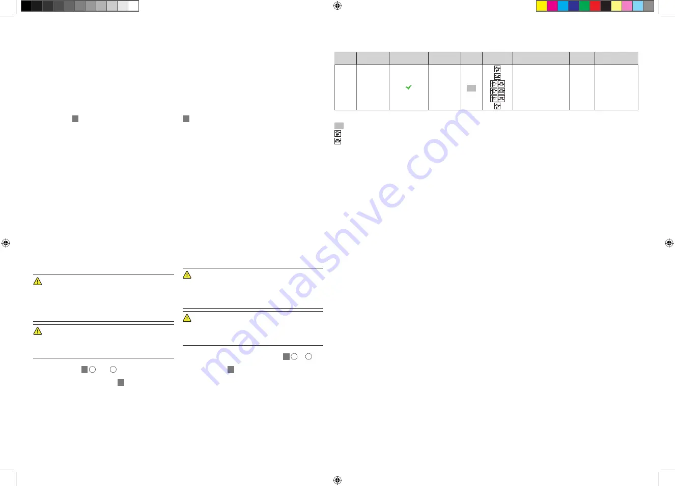
Technische Daten
Technical data
Art.-Nr.
Item.-No.
Typ
Type
Zwischenplatte
Intermediate plate
Abmessungen
Dimensions
Material
Material
Anordnung
Arrangement
Leiter 1 / Leiter 2
Conductor 1 / Cond. 2
Getestet*
Tested*
Anzugsdrehmoment
Tightening torque
5311590 249 8-10x16 VA
40 x 50 mm
V2A
Rd 8-10 FT / Rd 16 FT
Rd 8 FT / RD 16 FT
RD 8 V4A / Rd 16 V4A
Rd 8 Al / Rd 16 Al
Rd 8 Cu / Rd 16 Cu
S 9 Al / Rd 16 Al**
H (100 kA)
N (50 kA)
H (100 kA)
H (100 kA)
H (100 kA)
H (100 kA)
36 Nm
20 Nm
20 Nm
36 Nm
20 Nm
20 Nm
Legende /
Legend
V2A
Edelstahl, rostfrei 1.4301 /
Stainless steel 1.4301
Kreuzverbindung
Parallelverbindung
Rd Rundleiter /
round cable
S Seil / rope
* getestet nach /
tested acc. to
IEC 62561-1 / EN 62561-1 (50164-1) / VDE 0185-561-1 (-201)
** nicht für den Einbau in Beton geeignet / not suitable for installation in concrete
02-250_MA_Vario-Schnellverbinder_249_8-10x16_DeEn_2022-04-07.indd 2
02-250_MA_Vario-Schnellverbinder_249_8-10x16_DeEn_2022-04-07.indd 2
07.04.2022 16:55:22
07.04.2022 16:55:22


