background image

GES R2

RU | 71

Демонтаж лючка GES R2  

26  Демонтаж лючка GES R2 

˜°˛˜˝˜˙ˆ˜


Внимание! Угроза для жизни, обусловленная электрическим 

током!


Контакт с электрическим током может привести к поражению им  

Возможны опасные и даже смертельные повреждения  

Электромонтажные и электротехнические работы могут проводиться 

только специально обученным персоналом! 

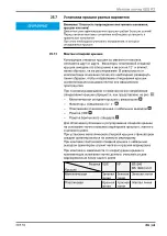
При демонтаже лючка GES R2 в первую очередь необходимо 

снять крышку  Затем основание лючка требуется извлечь из 

отверстия в полу  Дальнейший демонтаж осуществляется вне 

отверстия в полу 

26

 .

Инструменты


– шуруповерт или


– отвертка


– нож

26

 .

Снятие крышки

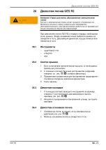
1   Если установлена металлическая крышка, то необходимо 

срезать ее уплотнитель 

2   С помощью соответствующих инструментов (например, 

отвертки, см  рис   , 

1

) ослабить фиксаторы 

3   Применение соответствующих инструментов предотвратит 

случайное повторное крепление фиксаторов 

4   Снять крышку 

26

 .

Демонтаж накладок

1   С помощью соответствующего инструмента (например, 

отвертки 7 мм) приподнять два фиксатора и вынуть 

накладку (см  рис   , 

2

2   Аккуратно поворачивая установленный штекер, вытащить 

накладки 

26

 .

Демонтаж основания лючка 

1   Ослабив три болта, вытащить их из универсальных 

креплений (см  рис   , 

1

2   Извлечь основание лючка из отверстия в полу 

Summary of Contents for GES R2

Page 1: ...Building Connections GES R2 DE Bodensteckdose EN Floor socket ES Toma de suelo RU Montageanleitung Mounting instructions Instrucciones de montaje...

Page 2: ...DE Inhaltsverzeichnis 10 EN Table of contents 26 ES ndice 42 RU 58...

Page 3: ...1 2 1 3 4 5 6 7 8 9 2...

Page 4: ...4 1 1 2 3 2 1...

Page 5: ...5 2 1 2 1 3 6 2 1...

Page 6: ...7 5 1 2 4 3...

Page 7: ...8 B1 C3 B4 B2 C1 B3 C2 A 4 5 1 3 2...

Page 8: ...9 3 2 1 10 1 2 5 4 3 6...

Page 9: ...11 12 12 0 2 3 1 4 2 3 5 4 12 1 1 1 2 2 2 3...

Page 10: ...it Installationsger ten 18 4 5 1 Installation mit Abdeckplatte 2 fach Modul 45 18 4 5 2 Installation mit zwei Abdeckplatten 1 fach Modul 45 18 4 5 3 Installation mit Abdeckplatte f r 1 5 fach Module 1...

Page 11: ...auf damit Sie sich bei Bedarf informieren k nnen 1 3 Typen von Sicherheitshinweisen WARNUNG Art der Gef hrdung Bezeichnet eine m glicherweise gef hrliche Situation Wenn sie nicht vermieden wird dann k...

Page 12: ...h berdeckten Ka nalsystemen estrichb ndigen Unterflurkan len und Systemb den Je nach Deckelvariante ist die Bodensteckdose f r trocken bzw nass gepflegte B den zugelassen 1 5 Zugrunde liegende Normen...

Page 13: ...e Sicherheitshinweise und Infor mationen zum Umgang mit der Bodensteckdose GES R2 Alle elektrotechnischen Montagearbeiten d rfen ausschlie lich von ausgebildetem Fachpersonal ausgef hrt werden Die Est...

Page 14: ...latte 2 fach Modul 45 vorbest ckt mit einer 2 fach Steckdose VDE oder NF siehe Abb 1 mit 1x Abdeckplatte 1 5 fach leer f r Steckdosen British Stan dard siehe Abb 2 Die Blindabdeckplatte siehe Abb 1 is...

Page 15: ...S R2 ben tigt Die Bodensteckdose GES R2 ist mit Zugentlastungen ausger stet Auch die zus tzlichen Daten und Multimedia Anschl sse sind von unten und von der Seite frei zug nglich Die Klappdeckel aus M...

Page 16: ...che Arbeiten d rfen nur von elektrotechnisch geschultem Fachpersonal durchgef hrt werden 4 1 Ben tigtes Werkzeug Akkuschrauber oder Schraubendreher 4 2 Voraussetzungen Bauseitig muss eine Boden ffnung...

Page 17: ...hlossen muss die Blindabdeckplatte durch die ben tigte Montageplatte f r Datenkabel ersetzt werden Hinweis Ist ein Teppichboden verlegt muss dieser f r die Deckelmontage im Bereich des Deckels herunte...

Page 18: ...deckplatte 2 fach Modul 45 aufstecken 2 Installationskabel elektrisch anschlie en 3 Zugentlastung in die Abdeckplatte 2 fach Modul 45 einsetzen 4 Installationskabel in die Zugentlastung einklemmen 5 M...

Page 19: ...se anschlie en 5 3 Die Datenbuchse von unten in das Datenmodul einstecken C2 4 Montierte Abdeckplatte 1 fach Modul 45 in die Installationsdo se einrasten C3 4 5 3 Installation mit Abdeckplatte f r 1 5...

Page 20: ...werden dass die Klapprichtung des Deckels dem Fugenbild oder der gew nschten Raumgestaltung entspricht Bei gleicher Positionierung der Installationsdose ergibt sich die Klapprichtung des Deckels wie i...

Page 21: ...Nur solche Deckel in nass gepflegte B den einbauen die f r die Nass pflege zugelassen sind Tubusdeckel Klappdeckel aus Metall und Blind deckel aus Metall Alle Deckel aus Metall m ssen zus tzlich mit...

Page 22: ...gt au erhalb der Boden ffnung 5 1 Ben tigtes Werkzeug Akkuschrauber oder Schraubendreher Messer 5 2 Deckel demontieren 1 Bei Deckeln aus Metall Dichtmasse aufschneiden 2 Die drei Rasthaken mit einem g...

Page 23: ...f r Installationsdose 122 mm Mindesteinbautiefe 85 mm Spannbereich 25 50 mm Ausf hrung Typ mit 2 fach Schutzkontakt Steckdose VDE MT R2 VDE 7408 83 2 mit 2 fach Erdungsstift Steckdose NF MT R2 NF 740...

Page 24: ...ppdeckel mit Rastschieber Typ GES R2 Material Zinkdruckguss galvanisierte Oberfl che Abmessung 140 x 140 x 40 mm Oberfl che vernickelt GES R2 Ni 7408 85 0 vermessingt GES R2 CuZn 7408 85 2 verkupfert...

Page 25: ...ssung 140 x 140 x 40 mm Farbe graphitschwarz GES R2 9011 7405 08 4 eisengrau GES R2 7011 7405 08 2 Sichtbare Deckelgr e 140 mm Gewicht 0 105 kg Blinddeckel Typ GES R2B Material Polyamid PA6 Abmessung...

Page 26: ...ent with accessories 34 11 5 1 Installation with 2x cover plate Modul 45 34 11 5 2 Installation with two 1x Modul 45 cover plates 34 11 5 3 Installation with cover plate for 1 5x modules 35 11 5 4 Ins...

Page 27: ...observe the safety inst ructions Keep all the documents supplied with the GES R2 floor socket safe so that the information is available should you need it 8 3 Types of safety information WARNING Type...

Page 28: ...creed covered duct systems screed flush underfloor ducts and system floors Depending on the lid variant the floor socket is approved for dry or wet cleaned floors 8 5 Basic standards The GES R2 floor...

Page 29: ...e following general safety information on handling the GES R2 floor socket Any electrical mounting work may only be carried out by trai ned specialist personnel The screed box for GES R2 item no 74285...

Page 30: ...2 3 With 1x cover plate double Modul 45 preequipped with a dou ble VDE or NF socket see Fig 1 With 1x cover plate 1 5x empty for British Standard sockets see Fig 2 The blanking cover plate see Fig 1...

Page 31: ...10 mm beneath the GES R2 floor socket is required The GES R2 floor socket is equipped with strain reliefs The additional data and multimedia connections are also freely accessible from below and from...

Page 32: ...k may only be carried by specialist personnel with electrical training 11 1 Required tools Battery operated screwdriver or screwdriver 11 2 Preconditions On the construction side there must be a floor...

Page 33: ...le are connected the blanking cover plate must be replaced with the required mounting plate for data cables Note If there is a carpeted floor this must be pushed down in the area of the lid for lid mo...

Page 34: ...to the 2x Modul 45 cover plate 2 Electrically connect the installation cable 3 Insert the strain relief in the 2x Modul 45 cover plate 4 Clamp the installation cable in the strain relief 5 Engage the...

Page 35: ...Insert the data socket into the data module from below C2 4 Engage the mounted 1x Modul 45 cover plate in the installation socket C3 11 5 3 Installation with cover plate for 1 5x modules 1 Attach the...

Page 36: ...must be rotated in such a way that the hinge direction of the lid corresponds to the joint pattern or the desired room design If the installation socket is positioned in the same place this produ ces...

Page 37: ...short cir cuits Only install those lids in wet care floors which are approved for wet care tube body lid metallic hinged lids and blanking lids All metallic lids must also be stuck to the base using...

Page 38: ...base opening 12 1 Required tools Battery operated screwdriver or screwdriver Knife 12 2 Dismantling the lid 1 For metallic lids Cut the sealing compound 2 Using a suitable tool unlock the three lockin...

Page 39: ...opening for installation socket 122 mm Minimum installation depth 85 mm Clamping range 25 50 mm Version Type with 2x protective contact socket VDE MT R2 VDE 7408 83 2 with 2x earthing pin socket NF MT...

Page 40: ...Hinged lid with locking slider Type GES R2 Material Die cast zinc galvanised surface Dimensions 140 x 140 x 40 mm Surface Nickel plated GES R2 Ni 7408 85 0 Brass coated GES R2 CuZn 7408 85 2 Copper pl...

Page 41: ...ns 140 x 140 x 40 mm Colour Graphite black GES R2 9011 7405 08 4 Iron grey GES R2 7011 7405 08 2 Visible lid size 140 mm Weight 0 105 kg Blanking lid Type GES R2B Material Polyamide PA6 Dimensions 140...

Page 42: ...con placa de cubierta Modul 45 doble 50 18 5 2 Instalaci n con dos placas de cubierta Modul 45 simple 50 18 5 3 Instalaci n con placa de cubierta para m dulos 1 5x 51 18 5 4 Instalaci n de cables de d...

Page 43: ...a informaci n relacionada con la toma de su elo GES R2 para que pueda utilizarla cuando la necesite 15 3 Tipos de indicaciones de seguridad ADVERTENCIA Tipo de peligro Describe una situaci n potencial...

Page 44: ...naliza ci n bajo pavimento canales a ras de pavimento y suelos modula res Seg n la variante de tapa la toma de suelo est autorizada para suelos que precisan una limpieza con agua o en seco 15 5 Normas...

Page 45: ...tes indicaciones generales de seguri dad e informaci n para el manejo de la toma de suelo GES R2 Cualquier trabajo de montaje electrot cnico solo puede ser efectuado por t cnicos debidamente formados...

Page 46: ...odul 45 doble preequipada con una toma de corriente doble VDE o NF v ase fig 1 con 1x placa de cubierta de 1 5x vac a para tomas de corri ente British Standard v ase fig 2 La tapa ciega v ase fig 1 se...

Page 47: ...de suelo GES R2 est equipada con descargas de tracci n Las conexiones adicionales de datos o multimedia tambi n son ac cesibles desde abajo o desde el lateral La tapa abatible de metal y de pl stico s...

Page 48: ...pueden ser realizados por t cnicos pro fesionales con formaci n en electrotecnia 18 1 Herramientas requeridas destornillador el ctrico o destornillador 18 2 Requisitos A cargo del propietario debe pra...

Page 49: ...la tapa ciega por la placa de montaje necesaria para cables de datos Nota Si hay una alfombra para montar la tapa debe presionarse hacia abajo en la zona de la tapa Para ello antes del montaje de la c...

Page 50: ...a placa de cubierta Mo dul 45 doble 2 Conectar el ctricamente el cable de instalaci n 3 Instalar la descarga de tracci n en la placa de cubierta Modul 45 doble 4 Fijar el cable de instalaci n en la de...

Page 51: ...ma de datos 5 3 Encajar la toma de datos desde abajo en el m dulo de datos C2 4 Encajar en la caja de instalaci n la placa de cubierta montada Modul 45 simple C3 18 5 3 Instalaci n con placa de cubier...

Page 52: ...o abatible de la tapa corresponda a la junta o a la distribuci n espacial deseada Con el mismo posicionamiento de la caja de instalaci n se obti ene el sentido abatible de la tapa como se representa e...

Page 53: ...En suelos que precisan una limpieza con agua instalar solo tapas homo logadas para la limpieza con agua tapa de tubo tapa abatible de metal y tapa ciega de metal Adem s todas las tapas de metal deben...

Page 54: ...amientas requeridas destornillador el ctrico o destornillador C ter 19 2 Desmontaje de la tapa 1 En tapas de metal cortar el sellante 2 Liberar los tres ganchos de cierre con una herramienta adecu ada...

Page 55: ...fundidad m nima de montaje 85 mm Rango de sujeci n 25 50 mm Versi n Tipo con toma de corriente toma de tierra doble VDE MT R2 VDE 7408 83 2 con toma de corriente clavija de puesta a tierra doble NF MT...

Page 56: ...n corredera deslizante tipo GES R2 Material cinc colado a presi n superficie galvaniz ada Tama o 140 x 140 x 40 mm Superficie Niquelado GES R2 Ni 7408 85 0 latonada GES R2 CuZn 7408 85 2 Ba ado en cob...

Page 57: ...a o 140 x 140 x 40 mm Color negro grafito GES R2 9011 7405 08 4 gris hierro GES R2 7011 7405 08 2 Tama o de tapa visible 140 mm Peso 0 105 kg Tapa ciega tipo GES R2B Material poliamida PA6 Tama o 140...

Page 58: ...62 24 1 62 24 2 62 25 GES R2 64 25 1 64 25 2 64 25 3 64 25 4 65 25 5 66 25 5 1 Modul 45 66 25 5 2 Modul 45 66 25 5 3 1 5 67 25 5 4 67 25 6 68 25 7 69 25 7 1 69 25 7 2 70 26 GES R2 71 26 1 71 26 2 71...

Page 59: ...GES R2 RU 59 22 22 1 GES R2 22 2 GES R2 22 3...

Page 60: ...60 RU 22 4 GES R2 22 5 GES R2 EN 50085 2 2 DIN VDE 0100 EN 50310 EN 50173 EN 50174 2...

Page 61: ...GES R2 RU 61 23 GES R2 GES R2 7428526...

Page 62: ...62 RU GES R2 24 GES R2 24 1 GES R2 6 7 8 9 1 5 2 4 2 Modul 45 2 3 1 Modul 45 VDE NF 1 1 1 5 2 1 1 2 3 4 5 24 2 GES R2 25 50 85...

Page 63: ...GES R2 RU 63 GES R2 GES R2 UD GES R2 GES R2 GES R2 Modul 45 VDE NF Modul 45 GES R2 GES R2 10 GES R2 12 2 Modul 45 1 VDE 4 Modul 45 3 VDE 4 1 5 3 5 GES R2...

Page 64: ...64 RU GES R2 25 GES R2 25 1 25 2 122 25 3 1 2 3...

Page 65: ...GES R2 RU 65 GES R2 25 4 25 7 auf Seite 69 10 2 1 1 2 2 3 3 2 4 5 1...

Page 66: ...66 RU GES R2 25 5 33 0 25 5 1 Modul 45 1 Modul 45 2 3 Modul 45 4 5 Modul 45 25 5 2 Modul 45 Modul 45...

Page 67: ...GES R2 RU 67 GES R2 A 1 1 2 3 B 1 Modul 45 B1 2 4 3 Modul 45 B2 4 B3 5 Modul 45 B4 C 1 Modul 45 C1 2 5 3 C2 4 Modul 45 C3 25 5 3 1 5 1 1 5 2 2 3 1 5 4 5 1 5 25 5 4 1 2 3...

Page 68: ...68 RU GES R2 25 6 1...

Page 69: ...GES R2 RU 69 GES R2 25 7 25 7 1 12 1 12 2 3 VDE 4 5 VDE NF BS 546 BS 1363 G...

Page 70: ...70 RU GES R2 25 7 2 1 2 3 2 1...

Page 71: ...GES R2 RU 71 GES R2 26 GES R2 GES R2 26 1 26 2 1 2 1 3 4 26 3 1 7 2 2 26 4 1 1 2...

Page 72: ...7 28 28 1 PA6 RAL 9011 131 x 131 x 85 122 85 25 50 VDE MT R2 VDE 7408 83 2 NF MT R2 NF 7408 83 4 2 Modul 45 MT R2 1 1 7408 83 8 1 5 MT R2 1 5 7408 83 6 28 2 c 205 x 180 x 85 122 85 85 130 UD GES R2 74...

Page 73: ...6 2 GES R2T Cu 7408 86 4 GES R2T Cr 7408 86 6 140 1 14 GES R2 140 x 140 x 40 GES R2 Ni 7408 85 0 GES R2 CuZn 7408 85 2 GES R2 Cu 7408 85 4 GES R2 Cr 7408 85 6 140 0 585 GES R2B 140 x 140 x 40 GES R2B...

Page 74: ...74 RU 28 3 2 GES R2 PA6 140 x 140 x 40 GES R2 9011 7405 08 4 GES R2 7011 7405 08 2 140 0 105 GES R2B PA6 140 x 140 x 40 GES R2B 9011 7405 08 8 GES R2B 7011 7405 08 6 140 0 082...

Page 75: ...GmbH Co KG Postfach 1120 58694 Menden Deutschland Kundenservice Deutschland Tel 02373 89 1500 Fax 02373 89 7777 E Mail info obo de www obo bettermann com OPTO 150862 Stand 01 2019 DE EN ES RU Buildin...

Reviews: