background image

OBO BETTERMANN

60 | EN

Mounting variants

6 4 

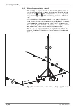
Lightning protection class I 

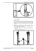
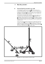
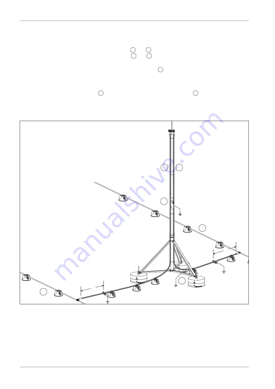
The mounting example shows a better division of the lightning current to 

two isCon cables through the use of an isFang interception rod with two 
external cables 

1

 and 

2

. The isCon cables are run on two separated 

ring conductors 

3

 and 

4

, which are run on opposite sides of the build-

ing.
The potential connection clip 

5

 (type 927 2 6-K) must be mounted, in 

order to create an electrical connection between the jacket of the external 
isCon cables and the interception rod. The potential is connected here. 

Alternatively, the potential can be connected at the interception rod stand 

6

, providing that the potential connection clip 

5

 is mounted.

The distance x (= separation distance s multiplied by two) between the 
potential connection terminals and the rear connection elements should 

be noted.

Rd 8

Rd 8

1

4

5

6

3

2

x

x

Figure 68:  

 Current division to two isCon cables, e.g. for lightning protection class 

I

Summary of Contents for isCon 750 LGR

Page 1: ...03 2014 EN isCon System instructions...

Page 2: ...BO BETTERMANN GmbH Co KG Reprinting even of extracts as well as photographic or electronic reproduction are prohibited isCon is a registered brand of OBO BETTERMANN GmbH Co KG OBO isCon System instruc...

Page 3: ...the isCon system 29 5 1 Cutting and removing the insulation of the isCon cable 29 5 1 1 Removing the light grey protective jacket isCon 750 LGR 29 5 1 2 Revealing the copper core for connection 30 5 2...

Page 4: ...rotection ring cable 58 6 2 Metallic roof attic 59 6 3 Internal and external isCon cable 60 6 4 Lightning protection class I 61 6 5 isCon cable included in the ring cable 62 7 Checking the lightning p...

Page 5: ...f these instructions Regional and seasonal factors were not taken into account To find out more about planning and installation using the OBO isCon system we recommend a comprehensive training course...

Page 6: ...ormity certify the agreement with the named standards and stored documents but do not however contain any guar antee of properties You can find individual proofs for lightning protection components on...

Page 7: ...ere is no guarantee that safe installation is possible The jacketing of the black OBO isCon cable may not be cut or dam aged An interruption in the external black conductive layer will prevent the cab...

Page 8: ...trical structures If there is a direct lightning strike the incoming energy is arrested through the isCon cable to the building s earthing system There is no direct arcing between the arrestor and the...

Page 9: ...EVA 6 External jacket light grey only for isCon 750 LGR Type isCon 750 SW isCon 750 LGR Colour Black Light grey Equivalent separation distance air 750 mm 750 mm Equivalent separation distance solid ma...

Page 10: ...ds or forwarding systems using system tested connection elements see also 5 2 Mount ing the isCon connect connection element on page 31 isCon 1 2 Figure 2 isCon cable in the interception rod with inte...

Page 11: ...ents Legend 1 Air termination rod 2 Insulated central rod 3 Retaining rod The metallic components of the rods are made of aluminium of stainless steel V2A The insulated central rod is made of glass fi...

Page 12: ...00 50 Alu GRP 1 isFang 3B 100 A isFang IN A 6000 5408 940 6000 50 Alu GRP isFang 3B 150 A isFang IN A 8000 5408 888 8000 50 Alu GRP isFang 3B 250 A isFang IN A 10000 5408 890 10000 50 Alu GRP isFang 3...

Page 13: ...ains folding interception rod stands of different sizes to allow the isFang interception rods to be mounted on flat roofs for example The tripod interception rod stands allow the erection of the inter...

Page 14: ...n cable isFang 3B 100 AL 5408 966 1000 40 600 885 Al isFang 3B 150 AL 5408 967 1500 40 900 1275 Al isFang 3B 100 5408 968 1000 40 600 885 V2A isFang 3B 150 5408 969 1500 40 900 1275 V2A Tab 3 Technica...

Page 15: ...3B 5403 238 Edge protection with gland hole Polyamide Threaded rod isFang 3B G1 5408 971 270 mm for 1 concrete block1 V2A Threaded rod isFang 3B G2 5408 972 340 mm for 2 concrete blocks1 V2A Threaded...

Page 16: ...t in conjunction with isFang TW200 4 V2A 6 isFang TR100 5408 956 40 50 Tightening strap clip for round construction pipes of 50 300 mm distance to pipe 40 mm V2A 6 isFang TR100 100 5408 955 40 50 Tigh...

Page 17: ...3 6 1483587 Galvanised terminal with M6 internal thread to fasten an isCon H VA cable bracket with M16x6 bolt 5 Roof cable bracket with adapter and M Quick cable bracket 165 MBG 8 165 MBG UH M Quick M...

Page 18: ...ution for cleaning the external jacket of the OBO isCon cable see Fig 23 on page 31 4 Potential connection terminal isCon PAE 5408 036 Potential connection of the isCon cable seat 17 25 mm V2A 5 Poten...

Page 19: ...on distance on page 22 Calculate the number of isCon cables and interception systems ac cording to the lightning protection class and required cable length see 4 3 Cable lengths and lightning protecti...

Page 20: ...ning an installation 4 1 Schematic diagram of the isCon system 1 m 1 3 4 5 6 7 8 9 2 5408 022 5336 058 5408 056 5408 036 5408 043 5408 952 5057 599 5058 022 5058 026 2332 784 Figure 12 Installation ex...

Page 21: ...nstalled in the manner descri bed in 5 7 Attaching the potential connection on page 50 The potential connection element must be connected to the equipotential bonding with 6 mm Cu or an equal conducti...

Page 22: ...the calculated separation distance s We recommend installing the cables at least 20 cm apart This keeps the magnetic fields to a minimum preventing the cables from influencing each other In the case...

Page 23: ...f 2 If the earther resistance of individual electrodes deviates by more than a factor of 2 kc 1 should be assumed Source DIN EN 62305 3 2011 Table 12 Installation for lightning protection class II As...

Page 24: ...pecial structures According to this planners craftspeople and testers of lightning protec tion systems must meet the following requirements and levels of knowl edge in potentially explosive areas Gene...

Page 25: ...System instructions OBO isCon EN 25 Planning an installation Zone 0 20 Zone 1 21 Zone 2 22 Figure 15 Example of the installation of the isCon system in the Ex zones of a potentially explosive area...

Page 26: ...uarantees a high degree of protec tion and can be routed safely under the soft roof Consult the roofer in order to have a waterproof penetration of the insu lated interception rod created Fasten the i...

Page 27: ...emnitz Dresden Halle Leipzig Magdeburg Berlin Hannover Kassel Bremen Hamburg Rostock Kiel 1 2 3 4 Figure 17 Wind speed zones in Germany Zone Wind speed in km h 1 127 2 145 3 162 4 185 Tab 9 Maximum wi...

Page 28: ...em no 5408 973 isFang 6000 AL Item no 5408 947 Alu GRP isFang 3B 150 AL Item no 5408 967 isFang 6000 Item no 5408 946 V2A GRP isFang 3B 150 Item no 5408 969 isFang IN 6000 Item no 5408 936 Alu GRP Wal...

Page 29: ...o be painted e g with the paint of the facade As the external light grey pro tective jacket is non conductive it must be removed in the contact areas Shorten the isCon cable on site to the required le...

Page 30: ...gure 19 Releasing the light grey outer jacketing within the cable routing 5 1 2 Revealing the copper core for connection Using the stripping tool isCon stripper 2 adjust the stripping length to 25 mm...

Page 31: ...ion terminal At the same time an electrical connec tion is created between the copper core and the black weakly conductive external jacket of the isCon cable Scope of delivery per packaging unit 2 con...

Page 32: ...ent Apply the screw lock varnish to the screw holes and tighten the two pin screws with approx 5 Nm 5 Nm Figure 25 Applying screw lock varnish and tightening the pin screws Pull the heat shrinkable sl...

Page 33: ...igure 27 Interception rod with internally routed isCon cable Legend 1 Air termination rod 2 Internal connection element 3 Isolated central rod 4 Potential connection with potential connection element...

Page 34: ...mm see also 5 1 Cutting and removing the insulation of the isCon cable on page 29 Using a stripping stool e g isCon stripper 2 reveal the copper core along a length of 25 mm 25 mm Figure 28 Cutting th...

Page 35: ...F 27 mm screw the isCon IN connect con nection element onto the isCon cable until the copper core can be seen completely in the two screw holes 27 mm 25 mm Figure 31 Screwing on the connection element...

Page 36: ...al bonding can be interrupted In the case of the grey cable jacket maintain a maximum cutting depth of 1 5 mm Measure 1500 mm from the bottom edge of the isCon IN connect con nection element Remove 50...

Page 37: ...h the side screw 20 Nm 20 Nm Figure 36 Fixing the air termination rod in the interception rod The internal potential connection element consists of two half shells These must be located in such a way...

Page 38: ...the half shells If necessary turn the half shells accordingly Figure 38 Pushing the retaining rod into the central rod Tighten the screws 20 Nm 20 Nm Figure 39 Connecting the insulated interception r...

Page 39: ...Figure 40 Interception rod with externally routed isCon cable Legend 1 Air termination rod 2 Connection plate 3 Top connection element 4 Insulated central rod 5 Potential connection with potential con...

Page 40: ...nnection element on page 31 Only for the light grey cable isCon 750 LGR To connect the potential connection element the light grey jacket in the contact area must be removed ATTENTION Risk of damage T...

Page 41: ...ate Tightening torque 24 Nm For two isCon cables on one interception rod use the connection plate for two cables type isCon AP2 16 VA Carry out connection in a similar manner to that described here 24...

Page 42: ...igure 44 Fastening the potential connection clip to the interception rod Next steps 5 4 Fastening the interception rod in the interception rod stand on page 43 or 5 5 Fastening the interception rod to...

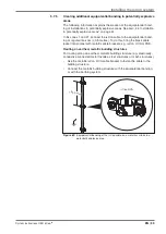
Page 43: ...the opening of the edge protection and the concrete plinth and fix it with the lock nut 5 4 2 Erecting the interception rod stand See also 3 3 Insulated interception rods on page 11 CAUTION Risk of c...

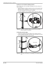
Page 44: ...ock nuts on the threaded rods Unfold the interception rod stand Fix the interception rod stand by screwing in the three locking screws and the spring washers Check that all the screws on the hinges fi...

Page 45: ...ositioning the interception rod stand Determine the inclination of the interception rod stand depending on the slope of the roof using a spirit level Compensate for the inclination of the interception...

Page 46: ...d Interception rod with internal isCon cable Insert the interception rod into the interception rod stand from above Figure 50 Inserting the interception rod in the interception rod stand Tighten the c...

Page 47: ...terception rod stand from above Tighten the clamp clip thus fixing the interception rod Figure 52 Fixing the interception rod in the interception rod stand In addition fasten the isCon cable to the in...

Page 48: ...external isCon cable Figure 53 Fastening interception rods to pipes walls or T supports Please note Fasten the interception rod to the building structure using the supports listed in Tab 5 on page 16...

Page 49: ...ng route changes maintain the minimum bend radius see Tab 1 on page 9 Route the isCon cable in such a way that it cannot be damaged by sharp edged objects If the isCon cable is damaged the entire sect...

Page 50: ...ounting a potential connection element e g clip clean the black jacket of the isCon cable from grease and other impurities to im prove the electrical conductivity using a cleaning cloth type isCon EPP...

Page 51: ...fix the cable and to earth it as well as to earth the interception rod and the interception rod stand If you are using an additional arrester to reduce the separation distance then observe the followi...

Page 52: ...terminal 4 in order to prevent surface discharge along the high voltage resistant isCon cable s x 2 3 1 4 Figure 56 Minimum distance x between the connection element and the equi potential bonding Not...

Page 53: ...ocate any electrically conductive or earthed parts within the calculated separation distance s in the area between the potential con nection and the connection element see Figure 56 These include for...

Page 54: ...quipotential bonding to the insulated interception rod stand 5 7 4 Installing additional potential connections If the isCon cable crosses earthed metallic installations or is run in parallel to them t...

Page 55: ...tervals 0 5 metres To do this bring the black cable jacket into contact with metallic cable brackets e g isCon H VA or PAE Routing on earthed metallic building structures For routing along an earthed...

Page 56: ...al bonding of the building Fasten the metallic isCon H VA cable bracket for the isCon cable to it 500 mm isCon H VA Figure 63 isCon cable in potentially explosive area with isCon H VA cable bracket mo...

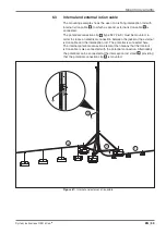
Page 57: ...terception rod via the potential connection clip 4 type 927 2 6 K Alternatively the potential can be connected at the interception rod stand 5 providing that the potential connection clip 4 is mounted...

Page 58: ...the interception rod via the potential connection clip 3 type 927 2 6 K Alternatively the potential can be connected at the interception rod stand 4 providing that the potential connection clip 3 is m...

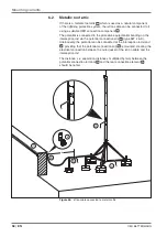
Page 59: ...K must be mounted in order to create an electrical connection between the jacket of the external isCon cable and the interception rod The potential is connected here The internal potential connection...

Page 60: ...clip 5 type 927 2 6 K must be mounted in order to create an electrical connection between the jacket of the external isCon cables and the interception rod The potential is connected here Alternativel...

Page 61: ...e difficult install whilst maintaining the required separation distance s e g to roof structures see Figure 69 No 2 the isCon cable 1 can be integrated into the mesh providing that s 0 75 metres s s s...

Page 62: ...ning protection systems in structures at risk of explo sion we recommend carrying out a visual inspection every 6 months Carrying out a visual inspection Check that the semi conductive jacket of the i...

Page 63: ...the separation distance maintained in the area between the connection element and the first potential connection of the OBO isCon cable 7 Is the potential connection connected to the local equipotent...

Page 64: ...t 46 Interception rod stand 13 Erect 43 isCon cable 8 Ring cable 61 isCon connect 31 isFang see Interception rod L Lightning protection classes 22 M Metallic roof attic 58 N Newsletter 5 P PEX cross l...

Page 65: ...System instructions OBO isCon EN 65 Own notes...

Page 66: ...OBO BETTERMANN 66 EN...

Page 67: ......

Page 68: ...OBO BETTERMANN GmbH Co KG PO Box 1120 58694 Menden Germany Customer Service Germany Tel 49 0 2373 891500 Fax 49 0 2373 897777 e mail info obo de www obo bettermann com OPTO 140143 Date 03 2014 EN...

Reviews: