System instructions OBO isCon
®
EN | 37
Installing the isCon® system
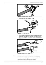
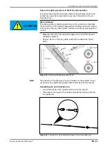
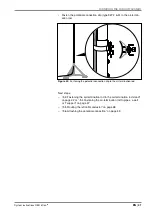
• Push the retaining rod as far as it will go into the central rod. In so
doing, the opening for the left copper screw (see Figure 38) may not
point to the gap between the half shells of the potential connection,
but centrally to one of the half shells. If necessary, turn the half shells
accordingly.
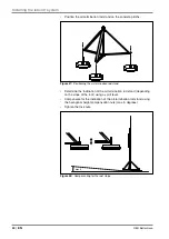
Figure 37:
Pushing the retaining rod into the central rod
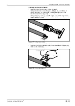
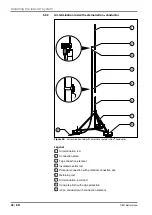
• Tighten the screws (20 Nm).
20 Nm
Figure 38:
Connecting the insulated air-termination rod and the retaining rod
Next steps:
– “„5.3 Fastening the air-termination rod in the air-termination rod stand“
on page 42 or “„5.4 Fastening the air-termination rod to pipes, a wall
or T support“ on page 47
– “„5.5 Routing the isCon® conductor“ on page 48
– “„5.6 Attaching the potential connection“ on page 49

