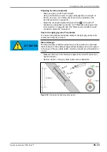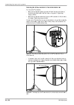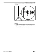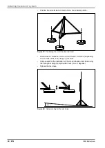
System instructions OBO isCon
®
EN | 53
Installing the isCon® system
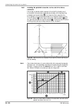
Legend for Figure 56:
1
Clip distance (x) from the potential connection terminal to the con-
nection element in centimetres
2
Calculated separation distance (s) in centimetres
A
isCon
®
BA 45 SW
B
isCon
®
ProPl 75 SW/LGR and isCon
®
Pro 75 SW
C
isCon
®
PR 90 SW
Example:
If the calculated separation distance is 60 cm, then you can use the vari-
ants isCon
®
Pro, ProPlus or Premium. Install the potential connection
terminal 120 cm in front of the connection element.
Note!
If the calculated separation distance is less than the appropriate tested
equivalent separation distance in air, you can reduce the distance be-
tween the potential connection terminal and the connection element (x)
accordingly.
If the calculated separation distance
2
is less than 17.5 centimetres (Pro,
ProPlus, Premium) and 20 centimetres (Basic), then no additional poten-
tial connection is required in front of the rear connection element.
Note!
The isCon conductor, type BA 45 SW (Basic), can either be installed with
or without a potential connection. If the conductor is installed without a
potential connection, the distance x must be maintained between the con-
nection element and the last insulated spacer and from this last spacer
in the direction of the other end of the conductor. Within the calculated
separation distance s, there must be no electrically conductive parts.
In addition, observe the following when connecting the equipotential
bonding:
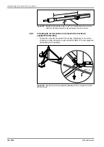
– Do not locate any electrically conductive or earthed parts within the
calculated separation distance s in the area between the potential con-
nection and the connection element (see Figure 55). These include,
for example, metallic construction parts, cable brackets and assem-
blies.
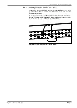
– Connect the potential connection terminal to the equipotential bonding
with ≥ 6 mm² Cu or a material with identical conductivity (see Figure
57).
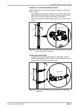
x
≥ 6 mm²
Figure 57:
Distance between the connection element and the potential connec-
tion terminal
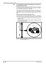
With metallic, earthed substrates, use the metallic cable bracket
isCon
®
H VA. When screwed directly to the substrate, it also provides
equipotential bonding.
Note!
When using the light grey isCon
®
conductor, the light grey protective jack-
et must be removed in the area of the cable bracket (see “„5.1.1 Removing
the light grey protective jacket (isCon® ProPI 75 LGR)“ on page 28).

