background image

11

308-028

Startup

CAUTION

The wallet sized warning card provided with the gun

should be kept with the operator at all times. The card

contains important information on reducing the risk of

a fluid injection injury , and treatment information

should an injection injury occur. Additional copies of

this card are available at no cost.

WARNING

Pressure Relief Procedure

To reduce the risk of serious injury, including fluid in-

jection, splashing in the eyes or on the skin, injury

from moving parts, or electric shock, always follow

this procedure whenever you shut of f the sprayer ,

when checking or servicing any part of the spray sys-

tem, when installing, cleaning or changing spray tips,

and whenever you stop spraying.
1. Shut off the sprayer and unplug it.
2. Hold a metal part of the gun firmly to the side of

a grounded metal pail, and trigger the gun into the

pail to relieve pressure.

3. Lock the trigger safety lever.
4. Turn the bypass valve 

counterclockwise

 one

turn to drain paint back into the pail.

If you suspect that the spray tip or hose is completely

clogged, or that pressure has not been fully relieved

after following the steps above,  very slowly loosen

the tip guard retaining nut or hose end coupling and

relieve pressure gradually, then loosen completely .

Now clear the tip or hose obstruction.

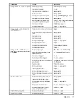
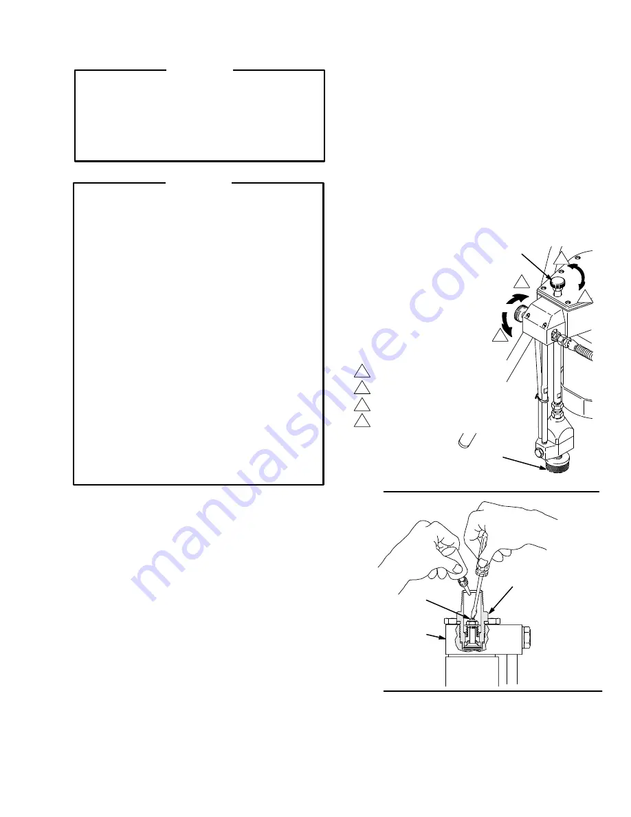
1. Open the bypass valve (66) ONE turn 

counter-

clockwise

. Do not place the pump intake in the pail

yet. See Fig. 3.

2. Turn the pressure control fully (4) 

clockwise

 to

increase the pressure. See Fig. 3.

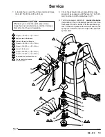
3. Remove the inlet strainer (27) and place your hand

over the inlet valve to be sure it is drawing a vacuum.

NOTE:

 If the inlet valve (26) is not drawing a vacuum,

turn the sprayer OFF. Turn the sprayer over. Press down

on the stem (A) inside the inlet valve lightly with a small

screwdriver, and pour about a teaspoon of mineral spirits

or solvent into the valve. See Fig. 4. Release the valve

and turn the sprayer upright. With the pressure turned up,

turn on the sprayer. This should free any sticking parts in

the pump. Now check again for a vacuum. Shut of f the

sprayer and install the inlet strainer (27).

4. Place the paint pump assembly into a properly pre-

pared 5 gallon pail of paint.

5. Turn the sprayer ON and allow the paint to circulate

through the bypass valve (4) for one or two minutes.

NOTE:

If the paint does not circulate back into the pail,

turn down the pressure and turn the motor on and off sev-

eral times to help prime the sprayer.

6. Turn the bypass valve (66) 

clockwise

 (finger tight)

to close it; this allows the pump to build up pressure.

1

3
4

2

Decrease the pressure 

(counterclockwise).
Increase the pressure (clockwise).
Open (counterclockwise).
Close (clockwise).

Fig. 3

Fig. 4

0271

0272

27

66

4

1

3

4

2

22

26

A

startup procedure continued on page 12

Summary of Contents for 223-635 C series

Page 1: ...z Model 223 635 Series C 3000 psi 210 bar Maximum Working Pressure U S Patent No 4 616 982 U K Patent No 2 165 591 Other Foreign Patents Pending THE O BRIEN CORPORATION 450 E Grand Avenue So San Franc...

Page 2: ...13 will result in leaking and damage to the sprayer Liquids can be injected into the body by high pressure airless spray or leaks especially hose leaks Keep body clear of the nozzle Never stop leaks...

Page 3: ...The pump reciprocates the hydraulic fluid to operate the dia phragm Diaphragm The diaphragm 21 separates the hydraulic and paint portions of the paint pump Hydraulic oil causes the dia phragm to move...

Page 4: ...fety lever in the locked or inoperative position TRIGGER View from front of gun 0268 Diffuser The gun diffuser breaks up spray and reduces the risk of fluid injection when the tip is not installed Che...

Page 5: ...ombined hose length to ensure grounding continuity See Hose Grounding Continuity below 3 Spray gun obtain grounding through connection to a prop erly grounded fluid hose and sprayer 4 Object being spr...

Page 6: ...elle quand l ajutage n est pas en place V rifier le fonctionnement du diffuseur r guli rement Pour cette v rifica tion d tendre la pression en observant la Marche Suivre Pour D tendre la Pressiondonn...

Page 7: ...EXPLOSION RISQUES D INCENDIE OU D EXPLOSION De l lectricit statique est produite par le passage du fluide grande vitesse dans la pompe et dans les tuyaux Si toutes les pi ces de l appareil de pulv ris...

Page 8: ...a Ver la ilustraci n m s abajo GATILLO Visto desde el frente de la pistola Pestillo de seguridad en la posicion abierta o rociando Pestillo de seguridad en la posicion cer rada o inoperante 0268 Difus...

Page 9: ...n guera 3 Pistola hacer la puesta a tierra conect ndola a una mangue ra de fluido y pulverizadora bien conectadas a tierra 4 Suministrar un recipiente de acuerdo al c digo local Usar solamente baldes...

Page 10: ...with light weight hydraulic oil use only Graco Hydraulic Oil Part No 218 797 Install the fill cap See Fig 1 5 Check the electrical service which must be 120V 60 HzAc 15 Amp minimum Be sure the electri...

Page 11: ...clear the tip or hose obstruction 1 Open the bypass valve 66 ONE turn counter clockwise Do not place the pump intake in the pail yet See Fig 3 2 Turn the pressure control fully 4 clockwise to increase...

Page 12: ...hen after each 25 hours of operation about weekly CAUTION Failure to properly tighten the inlet valve and screws at the intervals indicated will result in oil leaking from the hydraulic system into th...

Page 13: ...n the sprayer to drain the paint Now turn off the sprayer See Fig 7 2 Place the paint pump in a grounded flushing pail of solvent 3 Check to be sure the trigger safety lever is set Re move the spray t...

Page 14: ...The oil should be 1 inch 25 mm from the top of the plate If the oils is lower add oil as necessary use only Graco lightweight hydrau lic oil part no 218 797 Reinstall the fill cap hand tight if you ar...

Page 15: ...ing the fluid pressure Using the lowest pressure necessary to get the results you want will help prolong the life of your sprayer and minimize paint lost by overspray For interior corners such as on a...

Page 16: ...int build up between needle and diffuser Disassemble and clean gun Spray gun leaks Worn seal or loose fluid fitting Repair gun order Kit no 218 588 tighten fluid fitting Spray gun won t spray or low o...

Page 17: ...nt pump Replace Sprayer sucks paint builds pres sure but pressure drops when gun No spray tip on gun Shut off sprayer and install tip sure but pressure drops when gun is triggered Spray tip orifice to...

Page 18: ...in the valve will cause performance problems 6 Install the housing 28b and torque to 125 150 in lb 14 17 N m 7 The last coil on one end of the spring is turned in Place this end over the stud in the...

Page 19: ...turn it on Run the sprayer for two minutes to fill the hydraulic sys tem Increase the pressure to maximum and turn the sprayer on and off four times to help rid the hydraulic system of air Fig 15 21...

Page 20: ...que to 40 45 in lb 54 60 N m Torque to 130 140 in lb 15 16 N m Apply tape to the top and bottom threads See Detail A page 22 Torque to 70 90 in lb 8 10 N m The tube must drop freely in the pipe 1 Appl...

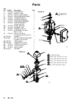
Page 21: ...40 CYLINDER pump 1 43 108 153 FITTING hose barbed 1 44 107 511 SPRING compression 1 45 180 479 PISTON 1 46 180 480 WASHER spring 1 47 107 517 RING retaining external 1 48 107 524 RING retaining extern...

Page 22: ...udes replaceable item 26a 1 26a 180 446 GASKET 1 28 236 954 OUTLET CHECK VALVE ASSY Includes items 28a 28f 1 28a 180 455 SEAL washer 1 28b 218 968 HOUSING seat valve 1 28c 112 619 SPRING compression 1...

Page 23: ...Delete Add Add 27 27 28 28 28c 28e 28c 28e 108 143 218 798 218 732 236 954 107 521 101 701 112 619 112 618 Strainer Strainer Outlet valve Outlet valve Spring Ball Spring Ball The complete old and new...

Page 24: ...ll Graco be liable for malfunction damage or wear caused by the incompatibility with Graco equipment of structures accessories equipment or materials not supplied by Graco or the improper design manuf...

Reviews: