background image

5

www.observint.com

© 2018 Observint Technologies. All rights reserved.

a. 

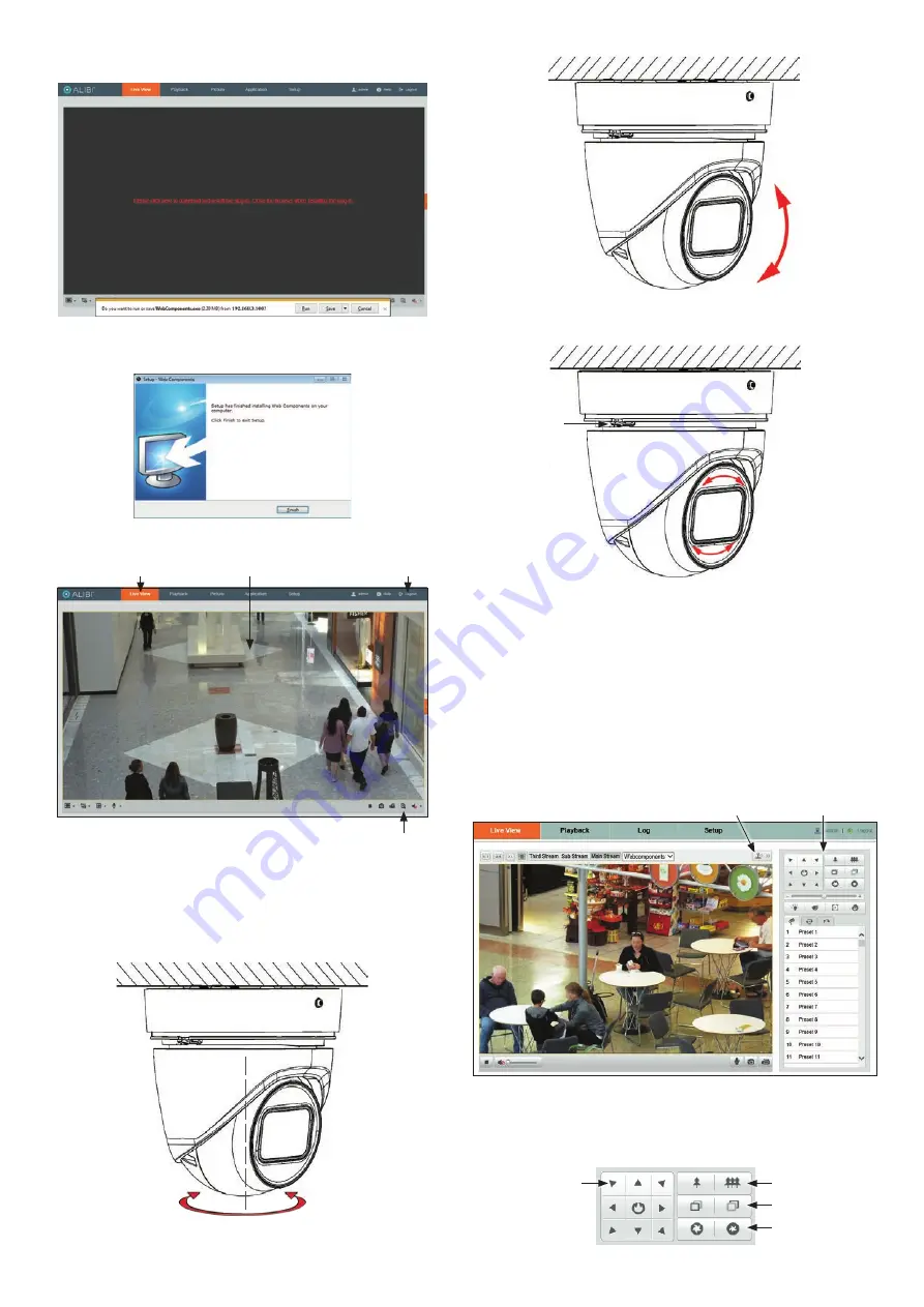
Click on the message to install the plugin. 

b. 

In the message bar at the bottom of the screen, click 

Run

. Follow the on-screen 

instructions to install 

WebComponents

. When the following screen opens, click 

Finish

The Live View screen with the camera video image should appear.

Capture, Record, Zoom icons

Screen select tabs

Logout button

Live View image

Step 7.  Adjust camera pan, tilt and rotation

Adjust the camera pan, tilt and rotation to point the camera at your surveillance target. When pointing 
the camera, use the 

Live View

 display on a recorder or remote login. 

1. 

To adjust the pan, grasp the camera at the sides of the camera and turn as needed. 

Pan range:  

0˚ ~ 355˚

To adjust the tilt, grasp the turret and tilt as needed for the image height. 

Tilt range:  

0˚ ~ 75˚

To adjust the rotation, grasp the turret and turn as needed for a horizontal image. 

Rotation range:  

0˚ ~ 360˚

Adjustment 

 screw

2. 

Tighten the adjustment screw to hold the turret in place. 

3. 

Reinstall the decorative ring. 

Step 8.  Verify PTZ functionality

Use the PTZ control panel to exercise the zoom and focus functionality of the camera. Accessing to the 
control panel depends on whether the camera is installed as a device on a LAN or if it is connected to a 
NVR. Select the installation type below for your camera to complete this step. 

For cameras installed on a LAN 

1. 

Log into the camera and then open the 

Live View

 window. 

Open / Close PTZ Control Panel

PTZ Control Panel

2. 

Click the joystick icon to open the PTZ control panel. See above. 

3. 

In the PTZ control panel, click each 

zoom

 and 

focus

 button shown in the graphic below. Verify 

that the camera performs as expected. Refer to the 

Specifications

 section of this document for 

zoom range. 

Direction buttons 

(not used)

Zoom In / Out

Focus In / Out

Iris Open / Close

Summary of Contents for ALIBI ALI-NS2112VR

Page 1: ...ation and locally record video and video captures Refer to the Specifications section for storage card requirements To install the card 1 Un package the camera and lay it upside down on a clean soft surface 2 Rotate the decorative ring to the left as shown in the drawing below and then remove it from the camera assembly Adjustment screw Decorative ring Adapter plate screw 3 Loosen the adjustment s...

Page 2: ...er plate can be secured to a single or double gang box b Remove the cover screws from the gang box c Align the screw holes in the adapter plate with the cover screw holes in the gang box and then secure the plate to the box with the cover screws removed previously For a double gang box use the screws through holes in the plate marked 1 For a single gang box use the screws through the holes in the ...

Page 3: ...ble for your NVR firmware for the procedure to activate the camera if necessary When an Alibi device is first installed or reset to its factory configuration it must be Activated before it can be used In the Alibi Configuration Tool Inactive devices have a Security status of Inactive and an IPv4 address of 192 168 1 64 A device is Activated when a password is assigned to the admin username of the ...

Page 4: ...r NVR skip this step Microsoft IE is used to access your camera remotely IE must run as an Administrator to use all features available through a remote login to the camera Setting MS Internet Explorer to run as an Administrator Window 7 To run IE as an Administrator 1 Find or create an IE icon on your computer desktop 2 Hold down the shift key and then right click on the IE icon MS Internet Explor...

Page 5: ... range 0 75 To adjust the rotation grasp the turret and turn as needed for a horizontal image Rotation range 0 360 Adjustment screw 2 Tighten the adjustment screw to hold the turret in place 3 Reinstall the decorative ring Step 8 Verify PTZ functionality Use the PTZ control panel to exercise the zoom and focus functionality of the camera Accessing to the control panel depends on whether the camera...

Page 6: ...View image in the menu Refer to the firmware user manual for your camera to use the other submenus on this screen For cameras connected directly to an NVR 1 Log into the NVR with administrative privileges 2 Open the firmware Image menu Go to Menu Camera Management Image 3 In the Camera field drop down list select the camera you want to configure In the example above D1 IPCamera 01 is selected 4 Dr...

Page 7: ... line Intrusion Detection Enter and loiter in a pre defined virtual region Unattended Baggage Objects left over in the pre defined region such as the baggage purse dangerous materials Object Removal Objects removed from the pre defined region such as the exhibits on display Recognition Face Detection General Operating Conditions 22 F 140 F 30 C 60 C Humidity 95 or less non condensing Power Supply ...

Reviews: