25
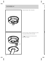
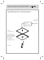
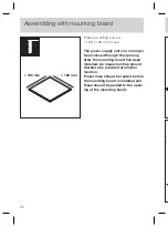
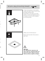
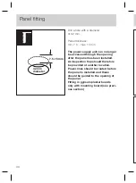
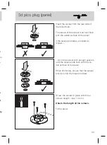
Fit the mounting board in the opening
correctly so that it is flush. To do so, use
the drilled holes provided.
If the board is to be fixed in any other
position, pre-drill holes before screwing
it in place in order to avoid damaging
the mounting board.
WARNING
The manufacturer expressly indi-
cates that if the mounting board has
not been properly fitted, it may fall,
thereby posing a significant danger.
Plaster over and sand the joins.
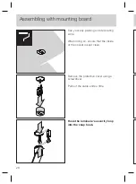
Ensure that the inside of the socket is
kept clean.
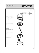
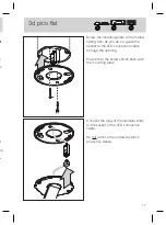
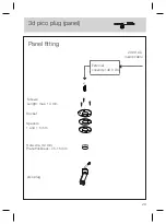
3d pico plug (mounting board)
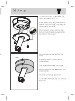
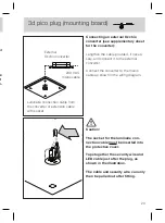
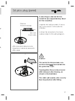
Caution:
The socket for the luminaire con-
nection cable must be inserted into
the protective cover.
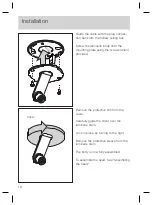
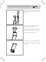
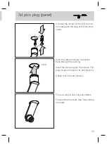
Tape together the security wire and
LED cable just after the plug, as
shown in the illustration.
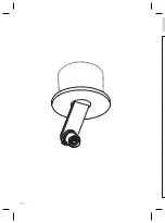
The cable and security wire can only
then be pulled out after fitting.
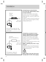
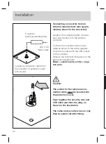
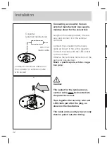
Connecting a converter from an
external manufacturer (see supple-
mentary sheet for the converter):
Lengthen the cable provided, if neces-
sary, and connect it to the external
converter.
Connect the converter to the mains
cable as shown in the wiring diagram.
Connect the cable with the LED socket
to the converter.
Observe the technical instructions of the
particular manufacturer.
Black = positive pole, white = nega-
tive pole
Summary of Contents for 3d body pico
Page 1: ...3d body pico Montageanleitung Mounting instructions up plug track...
Page 2: ......
Page 3: ...3d body pico Montageanleitung up flat plug track De...
Page 4: ...2...
Page 8: ...6 3 f V 3 f V 3 f V f V 3 f V...
Page 10: ...8 2 N...
Page 16: ...14 H...
Page 21: ...19 l t m...
Page 22: ...20...
Page 30: ...28...
Page 38: ...36 E 1 S 3 2 1 0...
Page 44: ...42...
Page 45: ...43 Anhang...
Page 48: ...46...
Page 49: ...3d body pico Mounting instructions up flat plug track En...
Page 50: ...2...
Page 54: ...6 3 f I 3 f E 3 f E f E 3 f I...
Page 56: ...8 2 m...
Page 62: ...14 H c...
Page 67: ...19 ng...
Page 68: ...20...
Page 76: ...28...
Page 84: ...36 E 1 b 3 2 1 0...
Page 90: ...42...
Page 91: ...43 Appendix...
Page 94: ...46...
Page 95: ......


