


Avoid these Situations For Your Personal Safety
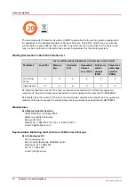
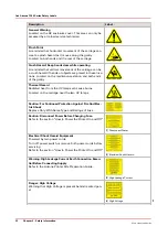
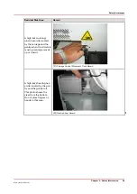
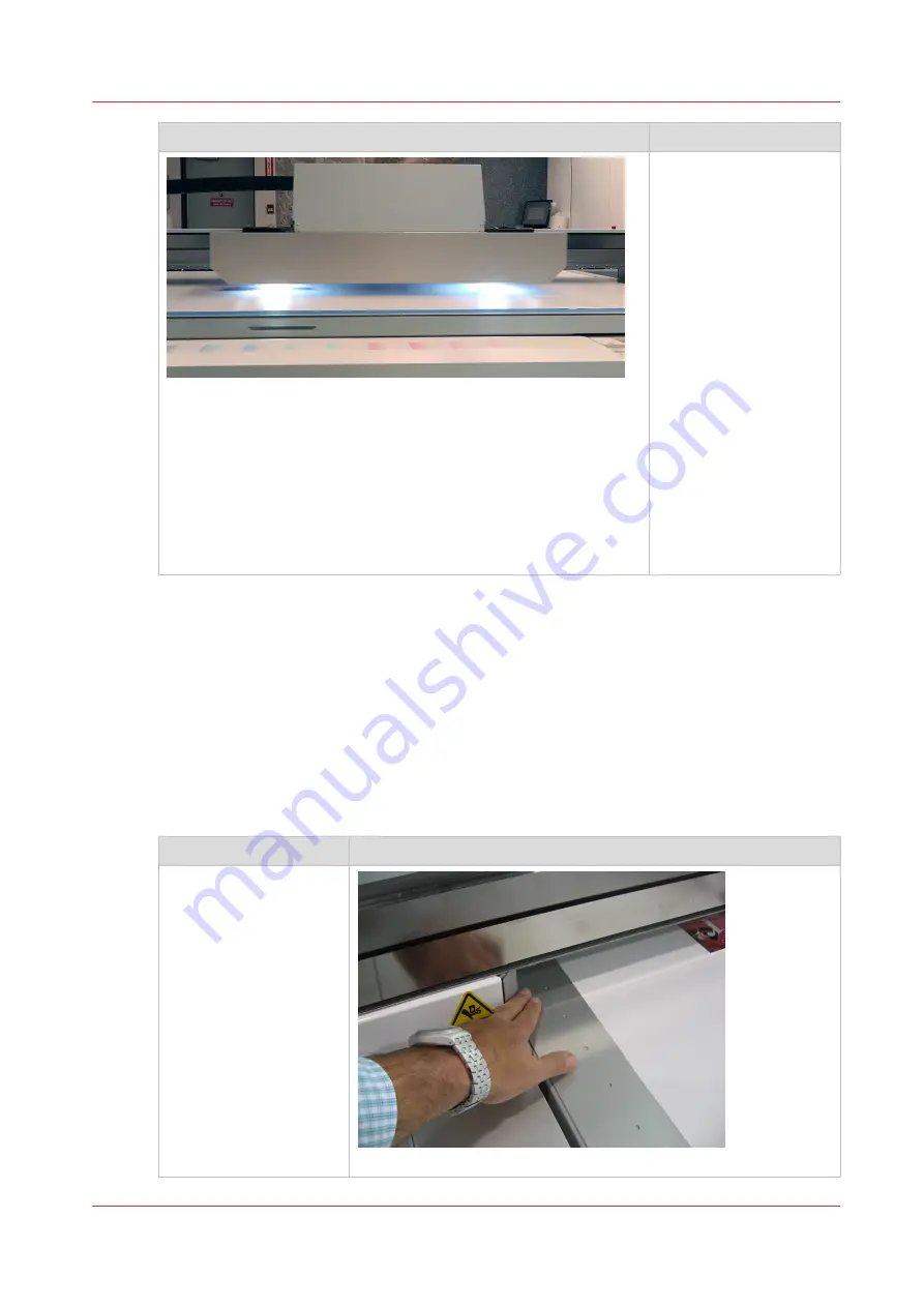
[16] UV Lamp Hazard
Avoid printing at a height
greater than measured as
this causes excessive
emissions of UV light
and ink mist.
Keep a distance of at
least 1 m (3 ft.) to the UV
light when printing.
Avoid looking at the UV
lamps, especially if you
are seated at the same
level as the carriage. Do
not sit within 5 meters
(17 feet) of the carriage
path.
Also do not touch the UV
lamp assembly or the
surrounding guard as
they will be hot and may
result in burns of the
skin.
Residual Safety Risks
Your Océ Arizona printer is engineered to minimize machine components and operating
procedures that may compromise operator safety. However, in order to maintain some machine
operations and functionality, certain compromises are required. The following table documents
some of these residual hazards. By making the operator aware of the potential risks, we hope to
ensure maximum safety in the operation of this printer.
Caution
: there may be a time lag between when a print job is issued and when the gantry
movement actually begins as the UV lamps must warm up first. Movement can start many
minutes after a print job is sent.
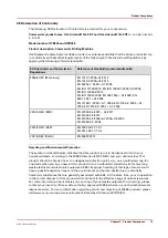
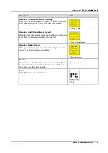
Arizona Printer Residual Risks
Residual Risk Area
Hazard
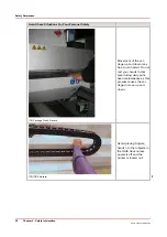
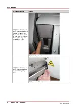
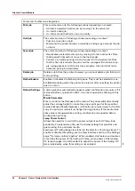
A high risk crushing haz-
ard is created by the
movement of the car-
riage and gantry sup-
ports. Keep hands away
from this area unless the
printer power is off.
[17] Carriage guard and 45° guard on Gantry Supports
4
Safety Awareness
Chapter 3 - Safety Information
27
Océ Arizona 1200 Series
Summary of Contents for arizona 1240 GT
Page 1: ...User guide Oc Arizona 1200 Series Revision 3010121377...
Page 6: ...Contents 6 Oc Arizona 1200 Series...
Page 7: ...Chapter 1 Introduction...
Page 11: ...Chapter 2 Product Compliance...
Page 15: ...Chapter 3 Safety Information...
Page 34: ...Roll Media Safety Awareness 34 Chapter 3 Safety Information Oc Arizona 1200 Series...
Page 35: ...Chapter 4 How to Navigate the User Interface...
Page 56: ...Software Update Module 56 Chapter 4 How to Navigate the User Interface Oc Arizona 1200 Series...
Page 57: ...Chapter 5 How to Operate Your Oc Arizona Printer...
Page 78: ...Media Registration 78 Chapter 5 How to Operate Your Oc Arizona Printer Oc Arizona 1200 Series...
Page 79: ...Chapter 6 Operating the Oc Arizona 1200 XT...
Page 85: ...Chapter 7 Roll Media Option...
Page 109: ...Chapter 8 Static Suppression Option...
Page 113: ...Chapter 9 How to Manage a White Ink Workflow...
Page 157: ...Chapter 10 Ink System Management...
Page 161: ...Chapter 11 Troubleshooting...
Page 163: ...Chapter 12 Printer Maintenance...
Page 207: ...Appendix A Application Information...


