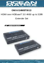
background image

1) Connect the source to the transmitter
2) Connect the display to the receiver
3) Connect a CAT6a/7 cable between the units
4) Connect the included power supply to either the transmitter or the receiver. 

Connection Instructions:

Summary of Contents for OMX-01HMBT0013

Page 1: ...OMX 01HMBT0013 HDMI over HDBaseT 3 0 4K60 up to 328ft Extender Set...

Page 2: ...st Device is Configurable Bi Directional 24V POC Function The Ocean Matrix OMX 01HMBT0013 is an HDBaseT 3 0 extender that can send uncompressed HD UHD video and audio signals eARC ARC RS 232 bi direct...

Page 3: ...Female 1 x SPDIF Out S PDIF 1 x L R Out 3 5mm Stereo Mini Jack TX Controls 1 x IR In 3 5mm Stereo Mini Jack 1 x IR Out 3 5mm Stereo Mini Jack 1 x RS 232 3 Pin 3 81 Phoenix Jack 1 x Service Mini USB U...

Page 4: ...out port is the loopout port for the HDMI in port switch to the right audio only the HDMI out port outputs 720p black screen image and the audio is from ARC or SPDIF Host Device USB Switch Switch to...

Page 5: ...USB Switch Switch to the left host the USB host mode is enables switch to the right device the USB device is enabled USB Devices Two USB device ports connected to UDISK mouse or keyboard USB Host USB...

Page 6: ...e source to the transmitter 2 Connect the display to the receiver 3 Connect a CAT6a 7 cable between the units 4 Connect the included power supply to either the transmitter or the receiver Connection I...

Page 7: ...ut routing are different for different scenarios as shown in the diagrams below 1 Set the Extender to SPDIF Mode Then switch the LOOP OUT AUDIO ONLY switch to right the HDMI OUT port of the transmitte...

Page 8: ...ort of the transmitter is set to LOOP OUT 5 Set the Extender to eARC Mode Then switch the LOOP OUT AUDIO ONLY switch to right the HDMI OUT port of the transmitter is set to AUDIO ONLY 6 Set the Extend...

Page 9: ...ing or de embedding through the L R IN OUT switch TX Audio Embedding When the L R IN OUT switch is switched to left the audio from external audio devices will be embedded to the L R IN OUT port TX Aud...

Page 10: ...mitter to set to USB Host mode Meanwhile switch the DEVICE HOST USB switch to left then power off and reboot the receiver to set to USB Device mode Mode 2 USB forward from RX to TX Switch the HOST DEV...

Page 11: ...onfiguration is as follows Note When the angle between the IR receiver and the remote control is 45 the transmission distance is 0 5 meters when the angle between the IR receiver and the remote contro...

Page 12: ...Application Example Diagram...

Page 13: ...ical shock and injury to persons To prevent fire or shock hazard do not expose the unit to rain moisture or install this product near water Never spill liquid of any kind on or into this product Never...

Reviews: