C-Nav7050 User Guide
Revision 0
Page 16 of 27
10/30/2020
Section 4
–Installation
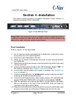
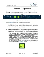
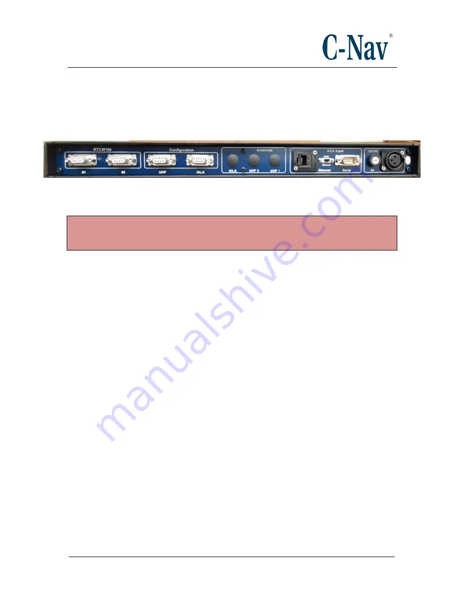
This section provides guidance on hardware installation. Figure 3 (Page
shows the rear panel of the C-Nav7050.
Figure 3: C-Nav7050 Rear Panel
Please note
: Prior to commencing any installation, discuss proposed mounting
locations / methods and cable routes with those involved to ensure all parties are
aware of the work to be done and the risks involved.
Rack Installation
Refer to Figure 1 for the steps below:
1)
If a 19” rack has not been provided, find a suitable rack on board the vessel
to mount the 1U (1.75”) tall C-Nav7050.
2) Secure the outer sliding rails to the rack.
3) If there are no front rack nuts already on the rack, use the nuts provided with
the C-Nav7050.
4) Slide the C-Nav7050 onto the rails, ensuring that the C-Nav7050 is secured
onto the outer rails.
5)
Connect the IALA antenna cable to the TNC receptacle labeled “
IALA”
(if
this option is installed). See
6) Connect UHF antenna cables (if this option is installed). See
7) Connect a serial cable from the
RTCM104
Out port(s) to each device that is
receiving the RTCM104 corrections data.
8) Connect the XLR plug from the power supply cable (or the optional power
supply kit P/N CNV7050PS-
OPT) to the power socket labeled “
12V DC
”.
9) Slide the rack back out, ensuring that there is enough slack for the cables
that are connected to the back of the C-Nav7050. Once you have the
necessary slack, dress up the cables.
10) Place the cover back on top of the C-Nav7050. Secure the six Phillips-head
screws on top and the seventh (also a Phillips-head) screw in the rear.

